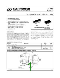
L297-L297D
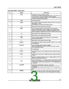
PIN FUNCTIONS - L297/L297D
N°
NAME
FUNCTION
1
SYNC
Output of the on-chip chopper oscillator.
The SYNC connections The SYNC connections of all L297s to be
synchronized are connected together and the oscillator
components are omitted on all but one. If an external clock source
is used it is injected at this terminal.
2
3
GND
Ground connection.
HOME
Open collector output that indicates when the L297 is in its initial
state (ABCD = 0101).
The transistor is open when this signal is active.
4
5
A
Motor phase A drive signal for power stage.
INH1
Active low inhibit control for driver stage of A and B phases.
When a bipolar bridge is used this signal can be used to ensure
fast decay of load current when a winding is de-energized. Also
used by chopper to regulate load current if CONTROL input is low.
6
7
8
B
C
Motor phase B drive signal for power stage.
Motor phase C drive signal for power stage.
INH2
Active low inhibit control for drive stages of C and D phases.
Same functions as INH1.
9
D
Motor phase D drive signal for power stage.
10
ENABLE
Chip enable input. When low (inactive) INH1, INH2, A, B, C and D
are brought low.
11
CONTROL
Control input that defines action of chopper.
When low chopper acts on INH1 and INH2; when high chopper
acts on phase lines ABCD.
12
13
Vs
5V supply input.
SENS2
Input for load current sense voltage from power stages of phases
C and D.
14
15
SENS1
Vref
Input for load current sense voltage from power stages of phases
A and B.
Reference voltage for chopper circuit. A voltage applied to this pin
determines the peak load current.
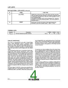
An RC network (R to VCC, C to ground) connected to this terminal
determines the chopper rate.This terminal is connected to ground
on all but one device in synchronized multi - L297 configurations. f
1/0.69 RC
16
17
OSC
CW/CCW
Clockwise/counterclockwise direction control input.
Physical direction of motor rotation also depends on connection
of windings.
Synchronized internally therefore direction can be changed at any
time.
18
CLOCK
Step clock. An active low pulse on this input advances the motor
one increment. The step occurs on the rising edge of this signal.
3/11

 STMICROELECTRONICS [ ST ]