HCC/HCF4051B/52B/53B
current. These multiplexer circuits dissipate ex-
tremely low quiescent power over the full VDD – VSS
and VDD – VEE supply-voltage ranges, independent
of the logic state ofthe control signals. When a-logic
”1” is present at the inhibit input terminal all channel
are off. The HCC/HCF4051B is a single 8-channel
multiplexer having three binary control inputs, A, B,
and C, and an inhibit input. The three binary signals
select 1 of 8 channels to be turned on, and connect
plexerhaving twobinary control inputs, Aand B,and
an inhibit input. The two binary input signals select
1 of 4 pairs of channels to be turned on and connect
the analog inputs to the outputs. The
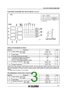
HCC/HCF4053B is a triple 2-channel multiplexer
having three separate digital control inputs, A, B,
and C, and an inhibit input. Each control input se-
lects one of a pair of channels which are connected
in a singlepole double-throw configuration.
one of the
8 inputs to the output. The
HCC/HCF4052B is a differential 4-channel multi-
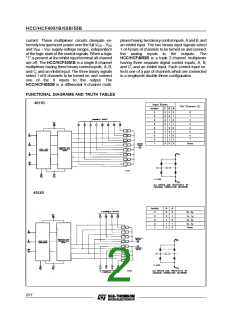
FUNCTIONAL DIAGRAMS AND TRUTH TABLES
4051B
Input States
”On” Channel (S)
Inhibit
C
0
0
0
0
1
1
1
1
X
B
0
0
1
1
0
0
1
1
X
A
0
1
0
1
0
1
0
1
X
0
0
0
0
0
0
0
0
1
0
1
2
3
4
5
6
7
None
4052B
Inhibit
B
A
0
0
0
0
1
0
0
1
1
X
0
1
0
1
X
0x, 0y
1x, 1y
2x, 2y
3x, 3y
None
2/17

 STMICROELECTRONICS [ ST ]