Application Hints
STV9302A
C performs an integration of the parabolic signal on C , therefore the amount of S correction is set
S
L
by the combination of C and C .
L
s
4.3
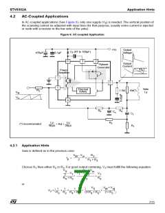
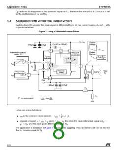
Application with Differential-output Drivers
Certain driver ICs provide the ramp signal in differential form, as two current sources i and i with
+
−
opposite variations.
Figure 7: Using a Differential-output Driver
+Vs
Output
Voltage
C (47 to 100µF)
F
470µF
0.1µF
6
3
2
Output
Current
Differential output
driver IC
Flyback
Generator
I
p
Power
Amplifier
i
p
+
7
+
i
i
cm
cm
5
R
7
1
-
Thermal
Safety
Yoke
Ly
1.5Ω
Rd(*)
-i
p
-
4
-V
EE
0.1µF
470µF
R
2
R
1
Ly
50µs
Ly
20µs
(*) recommended:
------------- < Rd < -------------
Let us set some definitions:
● i is the common-mode current:
1
2
i
= --(i + i )
cm
cm
+
-
● at peak of signal, i = i
+ i and i = i
- i , therefore the peak differential signal is i - (-
p p
+
cm
p
−
cm
i ) = 2 i , and the peak-peak differential signal, 4i .
p
p
p
The application is described in Figure 7 with DC yoke coupling. The calculations still rely on the fact
that V remains equal to V .
1
7
8/15

 STMICROELECTRONICS [ ST ]