A d v a n c e I n f o r m a t i o n
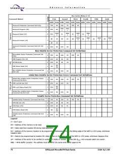
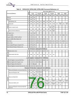
Bus Cycles (Notes 2–5)
Third Fourth
Addr Data Addr Data Addr Data Addr Data Addr Data Addr Data
Command (Notes)
First
Second
Fifth
Sixth
Password Protection Command Set Entry
3
2
555
XXX
AA
A0
2AA
55
555
60
PWA
x
PWD
x
Password Program (20)
Password Read (19)
PWD
0
PWD
1
PWD
2
PWD
3
4
7
2
XXX
01
00
02
00
03
01
PWD
0
PWD
1
PWD
2
PWD
3
00
00
25
29
90
03
02
03
Password Unlock (19)
Password Protection Command Set Exit (18,
23)
XXX
XXX
00
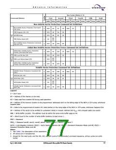
Non-Volatile Sector Protection Command Set Definitions
Nonvolatile Sector Protection Command Set
Entry
3
555
AA
2AA
55
555
C0
PPB Program (24, 25)
All PPB Erase
2
2
XXX
XXX
A0
80
SA
00
00
30
RD
(0)
PPB Status Read (25)
1
2
SA
Non-Volatile Sector Protection Command Set
Exit (18)
XXX
90
XXX
00
Global Non-Volatile Sector Protection Freeze Command Set Definitions
Global Non-Volatile Sector Protection Freeze
Command Set Entry
3
2
1
555
XXX
XXX
AA
A0
2AA
XXX
55
00
555
50
PPB Lock Bit Set (25)
RD
(0)
PPB Lock Status Read (25)
Global Non-Volatile Sector Protection Freeze
Command Set Exit (18)
2
XXX
90
XXX
00
Volatile Sector Protection Command Set Definitions
Volatile Sector Protection Command Set Entry
DYB Set (24, 25)
3
2
2
555
XXX
XXX
AA
A0
A0
2AA
SA
55
00
01
555
E0
DYB Clear (25)
SA
RD
(0)
DYB Status Read (25)
1
2
SA
Volatile Sector Protection Command Set Exit
(18)
XXX
90
XXX
00
Legend:
X = Don’t care
RA = Address of the memory to be read.
RD = Data read from location RA during read operation.
PA = Address of the memory location to be programmed. Addresses latch on the falling edge of the WE# or CE# pulse, whichever
happens later.
PD = Data to be programmed at location PA. Data latches on the rising edge of the WE# or CE# pulse, whichever happens first.
SA = Address of the sector to be verified (in autoselect mode) or erased. Address bits Amax–A16 uniquely select any sector.
WBL = Write Buffer Location. The address must be within the same write buffer page as PA.
74
S29GLxxxN MirrorBitTM Flash Family
27631A4 May 13, 2004

 SPANSION [ SPANSION ]