Integrated USB 2.0 Compatible 7-Port Hub
Datasheet
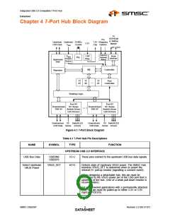
Chapter 4 7-Port Hub Block Diagram
To
EEPROM
or SMBus
Master
Pin
Upstream Upstream 24 MHz
1.8V Strapping
Cap Options
3.3V
USB Data
VBUS
Crystal
SD SCL
Internal
Defaults
Select
VBUS
Power
Detect
1.8V
Reg.
Serial
Interface
PLL
Upstream
PHY
Controller
SIE
Repeater
TT
#1
TT
#2
TT
#7
Port
Controller
...
Routing Logic
Port #1
Port #7
Downstream
PHY #1
OC Sense
Switch Driver
LED Drivers
Downstream
PHY #7
OC Sense
Switch Driver
LED Drivers
...
Downstream OC Switch/LED
USB Data Sense Drivers
Downstream
USB Data
OC Switch/LED
Sense Drivers
Figure 4.1 7-Port Block Diagram
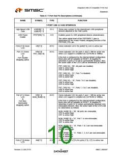
Table 4.1 7-Port Hub Pin Descriptions
TYPE FUNCTION
NAME
SYMBOL
UPSTREAM USB 2.0 INTERFACE
USB Bus Data
USBDN0
USBDP0
IO-U
These pins connect to the upstream USB bus data signals.
Detect Upstream
VBUS Power
VBUS_DET
I/O12
Detects state of Upstream VBUS power. The SMSC Hub
monitors VBUS_DET to determine when to assert the
internal D+ pull-up resistor (signalling a connect event).
When designing a detachable hub, this pin must be
connected to the VBUS power pin of the USB port that is
upstream of the hub. (Use of a weak pull-down resistor is
recommended.)
For self-powered applications with a permanently attached
host, this pin must be pulled-up to either 3.3V or 5.0V
(typically VDD33).
SMSC USB2507
9
Revision 2.3 (08-27-07)
DATASHEET

 SMSC [ SMSC CORPORATION ]