Integrated USB 2.0 Compatible 7-Port Hub
Datasheet
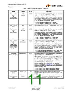
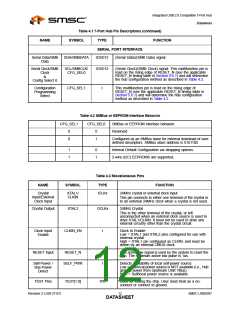
Table 4.1 7-Port Hub Pin Descriptions (continued)
NAME
SYMBOL
TYPE
FUNCTION
Port 4 Amber
LED
AM4/
LED_EN
I/O12
Amber indicator LED for port 4. Will be active low when LED
support is enabled via EEPROM or SMBus.
&
If the hub is configured by the internal default configuration,
this pin will be sampled at RESET_N negation to determine
if LED support is enabled or disabled. Also, the active state
of the LED will be determined as follows:
LED Enable
strapping option
‘0’ = LED support is disabled, LED is inactive
‘1’ = LED Support is enabled, LED is active low.
Port 3 Amber
LED
AM3
I/O12
I/O12
Amber indicator LED for port 3. Signal will be active low.
Port 2 Amber
AM2/
MTT_EN
Amber indicator LED for port 2. Will be active low when LED
support is enabled via EEPROM or SMBus.
LED
&
MTT Disable
If the hub is configured by the internal default configuration,
this pin will be sampled at RESET_N negation to determine
if MTT support is disabled (STT only). Also, the active state
of the LED will be determined as follows:
‘0’ = MTT support is disabled, LED is active high
‘1’ = MTT support is enabled, LED is active low.
Port 1 Amber
LED
AM1/
GANG_EN
I/O12
Amber indicator LED for port 1, Will be active low when LED
support is enabled via EEPROM or SMBus.
&
If the hub is configured by the internal default configuration,
this pin will be sampled at RESET_N negation to determine
if downstream port power switching and current sensing are
ganged, or individual port-by-port. Also, the active state of
the LED will be determined as follows:
Gang Power
Switching and
Current Sensing
strapping option.
‘0’ = Port-by-port sensing & switching, LED is active high
‘1’ = Ganged sensing & switching, LED is active low.
Port Power
Polarity strapping.
PRTPWR_POL
I/O12
Port Power Polarity strapping determination for the active
signal polarity of the 7:1PRTPWR pins.
While RESET_N is asserted, the logic state of this pin will
(though the use of internal combinatorial logic) determine
the active state of the 7:1PRTPWR pins in order to ensure
that downstream port power is not inadvertently enabled to
inactive ports during a hardware reset.
On the rising edge of RESET_N (see the applicable
RESET_N timing table in Section 5.6.1), the logic value will
be latched internally, and will retain the active signal polarity
for the PRTPWR7:1 pin.
‘1’ = PRTPWR7:1 pins have an active ‘high’ polarity
‘0’ = PRTPWR7:1 pins have an active ‘low’ polarity
Over Current
Sense
OCS7:1_N
RBIAS
IPU
I-R
Input from external current monitor indicating an over-
current condition. {Note: Contains internal pull-up to 3.3V
supply}
USB Transceiver
Bias
A 12.0kΩ (+/− 1%) resistor is attached from ground to this
pin to set the transceiver’s internal bias settings.
SMSC USB2507
Revision 2.3 (08-27-07)
DATAS11HEET

 SMSC [ SMSC CORPORATION ]