Integrated USB 2.0 Compatible 7-Port Hub
Datasheet
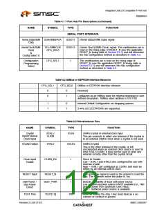
Table 4.3 Miscellaneous Pins (continued)
TYPE FUNCTION
NAME
SYMBOL
Analog Test
&
ATEST/
REG_EN
AIO
This signal is used for testing the analog section of the
chip, and to enable or disable the internal 1.8v regulator.
Internal 1.8V
voltage
regulator
enable
This pin must be connected to VDDA33 to enable the
internal 1.8V regulator, or to VSS to disable the internal
regulator.
When the internal regulator is enabled, the 1.8V power
pins must be left unconnected, except for the required
bypass capacitors.When the PHY is in test mode, the
internal regulator is disabled and the ATEST pin
functions as a test pin.
Table 4.4 Power, Ground, and No Connect
NAME
SYMBOL
TYPE
FUNCTION
VDDCORE3P3
VDD33CR
+3.3V I/O Power.
If the internal core 1.8V regulator is enabled, then this pin
acts as the regulator input
VDD1P8
VDD18
+1.8V core power.
If the internal regulator is enabled, then VDD18 pin 50
must have a 4.7μF (or greater) ±20% (ESR <0.1Ω)
capacitor to VSS
VDDAPLL3P3
VDDAPLL1P8
VDDA33PLL
VDDA18PLL
+3.3V Filtered analog power for the internal PLL
If the internal PLL 1.8V regulator is enabled, then this pin
acts as the regulator input
+1.8V Filtered analog power for internal PLL.
If the internal regulator is enabled, then this pin must
have a 4.7μF (or greater) ±20% (ESR <0.1Ω) capacitor
to VSS
VDDIO3P3
VDDA3P3
VSS
VDD33
VDDA33
VSS
+3.3V I/O power.
+3.3V Filtered analog power.
Ground.
Table 4.5 Buffer Type Descriptions
DESCRIPTION
BUFFER
I
Input.
IPD
IPU
IS
Input, with a weak Internal pull-down.
Input, with a weak Internal pull-up.
Input with Schmitt trigger.
Output 12mA.
O12
SMSC USB2507
Revision 2.3 (08-27-07)
DATA1S3HEET

 SMSC [ SMSC CORPORATION ]