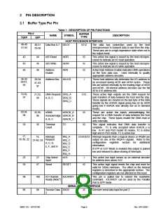
PIN #
BUFFER
TYPE
NAME
SYMBOL
DESCRIPTION
TQFP
QFP
87
89
Transmit Data TXD2
2
O12PD
Transmit serial data output for port 2.
(Note4)
76
77
78
79
Receive Data RXD1
I
Receiver serial data input for port 1.
Transmit serial data output for port 1.
1
Transmit Data TXD1
1
O12
O6
79,89
81,91
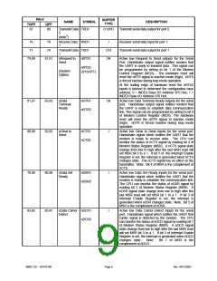
nRequest to
nRTS1
Active low Request to Send outputs for the Serial
Port. Handshake output signal notifies modem that
the UART is ready to transmit data. This signal can
be programmed by writing to bit 1 of the Modem
Control Register (MCR). The hardware reset will
reset the nRTS signal to inactive mode (high). nRTS
is forced inactive during loop mode operation.
Send
nRTS2
(SYSOPT)
(System
Option)
At the trailing edge of hardware reset the nRTS2
inputs is latched to determine the configuration base
address: 0 = INDEX Base I/O Address 3F0 Hex; 1 =
INDEX Base I/O Address 370 Hex.
81,91
80,90
83,93
82,92
nData
nDTR1
nDTR2
O6
Active low Data Terminal Ready outputs for the serial
port. Handshake output signal notifies modem that
the UART is ready to establish data communication
link. This signal can be programmed by writing to bit 0
of Modem Control Register (MCR). The hardware
reset will reset the nDTR signal to inactive mode
(high). nDTR is forced inactive during loop mode
operation.
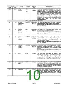
Active low Clear to Send inputs for the serial port.
Handshake signal which notifies the UART that the
modem is ready to receive data. The CPU can
monitor the status of nCTS signal by reading bit 4 of
Modem Status Register (MSR). A nCTS signal state
change from low to high after the last MSR read will
set MSR bit 0 to a 1. If bit 3 of the Interrupt Enable
Register is set, the interrupt is generated when nCTS
changes state. The nCTS signal has no effect on the
transmitter. Note: Bit 4 of MSR is the complement of
nCTS.
Terminal
Ready
nClear to
Send
nCTS1
nCTS2
I
78,88
83,85
80,90
85,87
nData Set
Ready
nDSR1
nDSR2
I
I
Active low Data Set Ready inputs for the serial port.
Handshake signal which notifies the UART that the
modem is ready to establish the communication link.
The CPU can monitor the status of nDSR signal by
reading bit 5 of Modem Status Register (MSR).
A
nDSR signal state change from low to high after the
last MSR read will set MSR bit 1 to a 1. If bit 3 of
Interrupt Enable Register is set, the interrupt is
generated when nDSR changes state. Note: Bit 5 of
MSR is the complement of nDSR.
nData Carrier nDCD1
Detect
Active low Data Carrier Detect inputs for the serial
port. Handshake signal which notifies the UART that
carrier signal is detected by the modem. The CPU
can monitor the status of nDCD signal by reading bit 7
of Modem Status Register (MSR). A nDCD signal
state change from low to high after the last MSR read
will set MSR bit 3 to a 1. If bit 3 of Interrupt Enable
Register is set, the interrupt is generated when nDCD
nDCD2
changes state.
Note:
Bit 7 of MSR is the
complement of nDCD.
SMSC DS – SP37E760
Page 9
Rev. 04/13/2001

 SMSC [ SMSC CORPORATION ]