D
D1
3
3
e
E
E1
W
5
2
D1/4
E1/4
DETAIL "A"
4
R1
R2
0
L
L1
A2
A
H
SEE DETAIL "A"
0.10
1
A1
-C-
DIM
A
NOM
MIN
MAX
1.6
A1
A2
D
0.05
1.35
15.75
13.90
15.75
13.90
1.40
16.00
14.00
16.00
14.00
1.45
16.25
14.10
16.25
14.10
0.20
D1
E
E1
H
L
0.60
1.00
0.50 BSC
0.45
0.75
L1
e
0
8°
0°
W
R1
R2
0.25
0.20
0.20
Notes:
1
2
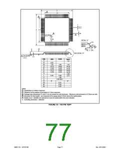
Coplanarity is 0.100mm maximum.
Tolerance on the position of the leads is 0.13mm maximum.
Package body dimensions D1 and E1 do not include the mold protrusion. Maximum mold protrusion is 0.25mm per side.
Dimension for foot length L are measured at the gauge plane 0.25mm above the seating plane.
Details of pin 1 identifier are optional but must be located within the zone indicated.
3
4
5
6. Controlling dimension: millimeter
FIGURE 18 – 100 PIN TQFP
SMSC DS – SP37E760
Page 77
Rev. 04/13/2001

 SMSC [ SMSC CORPORATION ]