5.4.5.3
Termination from ECP Mode
Termination from ECP Mode is similar to the termination from Nibble/Byte Modes. The host is permitted to terminate
from ECP Mode only in specific well-defined states. The termination can only be executed while the bus is in the
forward direction. To terminate while the channel is in the reverse direction, it must first be transitioned into the
forward direction.
5.4.5.4
Command/Data
ECP Mode supports two advanced features to improve the effectiveness of the protocol for some applications. The
features are implemented by allowing the transfer of normal 8 bit data or 8-bit commands (Table 21).
When in the forward direction, normal data is transferred when HostAck is high and an 8 bit command is transferred
when HostAck is low.
The most significant bit of the command indicates whether it is a run-length count (for compression) or a channel
address.
When in the reverse direction, normal data is transferred when PeriphAck is high and an 8 bit command is transferred
when PeriphAck is low. The most significant bit of the command is always zero. Reverse channel addresses are
seldom used and may not be supported in hardware.
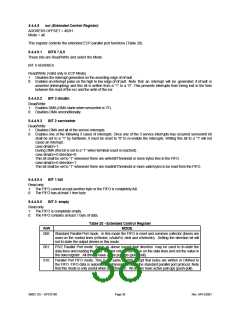
Table 21 - Forward Channel Commands (HostAck Low) Reverse Channel Commands (PeripAck Low) Data
Compression
D7
0
D[6:0]
Run-Length Count (0-127)
(mode 0011 0X00 only)
1
Channel Address (0-127)
The SP37E760 supports run length encoded (RLE) decompression in hardware and can transfer compressed data to
a peripheral. Run length encoded (RLE) compression in hardware is not supported. To transfer compressed data in
ECP mode, the compression count is written to the ecpAFifo and the data byte is written to the ecpDFifo.
Compression is accomplished by counting identical bytes and transmitting an RLE byte that indicates how many times
the next byte is to be repeated. Decompression simply intercepts the RLE byte and repeats the following byte the
specified number of times. When a run-length count is received from a peripheral, the subsequent data byte is
replicated the specified number of times. A run-length count of zero specifies that only one byte of data is represented
by the next data byte, whereas a run-length count of 127 indicates that the next byte should be expanded to 128
bytes. To prevent data expansion, however, run-length counts of zero should be avoided.
5.4.5.5
Pin Definition
The drivers for nStrobe, nAutoFd, nInit and nSelectIn are open-collector in mode 000 and are push-pull in all other
modes.
5.4.5.6
ISA Connections
The interface can never stall causing the host to hang. The width of data transfers is strictly controlled on an I/O
address basis per this specification. All FIFO-DMA transfers are byte wide, byte aligned and end on a byte
boundary. (The PWord value can be obtained by reading Configuration Register A, cnfgA, described in the next
section). Single byte wide transfers are always possible with standard or PS/2 mode using program control of the
control signals.
5.4.5.7
Interrupts
The interrupts are enabled by serviceIntr in the ecr register.
serviceIntr = 1 Disables the DMA and all of the service interrupts.
serviceIntr = 0Enables the selected interrupt condition. If the interrupting condition is valid, then the interrupt is
generated immediately when this bit is changed from a 1 to a 0. This can occur during Programmed I/O if the number
of bytes removed or added from/to the FIFO does not cross the threshold.
The interrupt generated is ISA friendly in that it must pulse the interrupt line low, allowing for interrupt sharing. After
a brief pulse low following the interrupt event, the interrupt line is tri-stated so that other interrupts may assert.
An interrupt is generated when:
1. For DMA transfers: When serviceIntr is 0, dmaEn is 1 and the DMA TC is received.
2. For Programmed I/O:
SMSC DS – SP37E760
Page 40
Rev. 04/13/2001

 SMSC [ SMSC CORPORATION ]