Advanced I/O Controller with Motherboard GLUE Logic
Datasheet
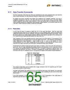
At the completion of the Read Data command, the head is not unloaded until after the Head Unload Time
Interval (specified in the Specify command) has elapsed. If the host issues another command before the
head unloads, then the head settling time may be saved between subsequent reads.
If the FDC detects a pulse on the nINDEX pin twice without finding the specified sector (meaning that the
diskette’s index hole passes through index detect logic in the drive twice), the FDC sets the IC code in
Status Register 0 to “01” indicating abnormal termination, sets the ND bit in Status Register 1 to “1”
indicating a sector not found, and terminates the Read Data Command.
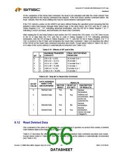
After reading the ID and Data Fields in each sector, the FDC checks the CRC bytes. If a CRC error occurs
in the ID or data field, the FDC sets the IC code in Status Register 0 to “01” indicating abnormal
termination, sets the DE bit flag in Status Register 1 to “1”, sets the DD bit in Status Register 2 to “1” if
CRC is incorrect in the ID field, and terminates the Read Data Command. Table 6.20 describes the effect
of the SK bit on the Read Data command execution and results. Except where noted in Table 6.20, the C
or R value of the sector address is automatically incremented (see Table 6.22).
Table 6.19 - Effects of MT and N Bits
MAXIMUM TRANSFER
CAPACITY
FINAL SECTOR READ
FROM DISK
26 at side 0 or 1
26 at side 1
15 at side 0 or 1
15 at side 1
8 at side 0 or 1
16 at side 1
MT
0
N
1
1
2
2
3
3
256 x 26 = 6,656
256 x 52 = 13,312
512 x 15 = 7,680
512 x 30 = 15,360
1024 x 8 = 8,192
1024 x 16 = 16,384
1
0
1
0
1
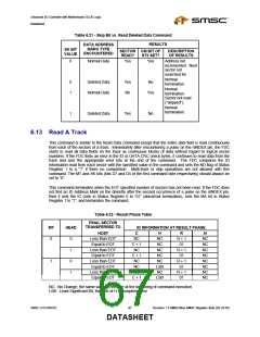
Table 6.20 - Skip Bit vs Read Data Command
DATA ADDRESS
RESULTS
MARK TYPE
SK BIT
VALUE
SECTOR CM BIT OF
DESCRIPTION
OF RESULTS
ENCOUNTERED
READ?
ST2 SET?
0
0
Normal Data
Yes
No
Normal
termination.
Address not
Deleted Data
Yes
Yes
incremented. Next
sector not
searched for.
Normal
1
1
Normal Data
Deleted Data
Yes
No
No
termination.
Normal
Yes
termination.
Sector not read
(“skipped”).
6.12 Read Deleted Data
This command is the same as the Read Data command, only it operates on sectors that contain a Deleted
Data Address Mark at the beginning of a Data Field.
Table 6.21 describes the effect of the SK bit on the Read Deleted Data command execution and results.
Except where noted in Table 6.21, the C or R value of the sector address is automatically incremented
(see Table 6.22).
Revision 1.8 SMSC/Non-SMSC Register Sets (02-24-05)
66
SMSC LPC47M182
DATASHEET

 SMSC [ SMSC CORPORATION ]