Advanced I/O Controller with Motherboard GLUE Logic
Datasheet
case dmaEn=1:
During DMA (this bit is set to a 1 when terminal count is reached).
case dmaEn=0 direction=0:
This bit shall be set to 1 whenever there are writeIntrThreshold or more bytes free in the FIFO.
case dmaEn=0 direction=1:
This bit shall be set to 1 whenever there are readIntrThreshold or more valid bytes to be read from
the FIFO.
BIT 1 full
Read only
1:
0:
The FIFO cannot accept another byte or the FIFO is completely full.
The FIFO has at least 1 free byte.
BIT 0 empty
Read only
1:
0:
The FIFO is completely empty.
The FIFO contains at least 1 byte of data.
Table 7.6 - Extended Control Register
MODE
R/W
000: Standard Parallel Port Mode . In this mode the FIFO is reset and common drain drivers are
used on the control lines (nStrobe, nAutoFd, nInit and nSelectIn). Setting the direction bit will
not tri-state the output drivers in this mode.
001: PS/2 Parallel Port Mode. Same as above except that direction may be used to tri-state the
data lines and reading the data register returns the value on the data lines and not the value
in the data register. All drivers have active pull-ups (push-pull).
010: Parallel Port FIFO Mode. This is the same as 000 except that bytes are written or DMAed to
the FIFO. FIFO data is automatically transmitted using the standard parallel port protocol.
Note that this mode is only useful when direction is 0. All drivers have active pull-ups
(push-pull).
011: ECP Parallel Port Mode. In the forward direction (direction is 0) bytes placed into the
ecpDFifo and bytes written to the ecpAFifo are placed in a single FIFO and transmitted
automatically to the peripheral using ECP Protocol. In the reverse direction (direction is 1)
bytes are moved from the ECP parallel port and packed into bytes in the ecpDFifo. All
drivers have active pull-ups (push-pull).
100: Selects EPP Mode: In this mode, EPP is selected if the EPP supported option is selected in
Parallel Port configuration register CRF0. All drivers have active pull-ups (push-pull).
101: Reserved
110: Test Mode. In this mode the FIFO may be written and read, but the data will not be
transmitted on the parallel port. All drivers have active pull-ups (push-pull).
111: Configuration Mode. In this mode the confgA, confgB registers are accessible at 0x400 and
0x401. All drivers have active pull-ups (push-pull).
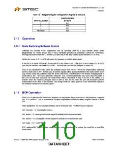
Table 7.7 – Programming for Configuration Register B (Bits 5:3)
CONFIG REG B
IRQ SELECTED
BITS 5:3
110
15
14
101
11
100
10
011
9
010
7
5
001
111
All Others
000
SMSC LPC47M182
109
Revision 1.8 SMSC/Non-SMSC Register Sets (02-24-05)
DATASHEET

 SMSC [ SMSC CORPORATION ]