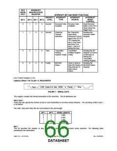
FIFO
MODE
ONLY
INTERRUPT
IDENTIFICATION
REGISTER
INTERRUPT SET AND RESET FUNCTIONS
PRIORITY INTERRUPT
INTERRUPT
SOURCE
INTERRUPT
LEVEL
TYPE
RESET
BIT 3
BIT 2 BIT 1 BIT 0
CONTROL
0
1
0
0
Second
Received Data Receiver Data
Read Receiver
Buffer or the FIFO
drops below the
trigger level.
Available
Available
1
1
0
0
Second
Character
Timeout
No Characters
Have Been
Reading the
Receiver Buffer
Indication
Removed From or Register
Input to the RCVR
FIFO during the
last 4 Char times
and there is at
least 1 char in it
during this time
0
0
0
0
1
0
0
0
Third
Transmitter
Holding
Register Empty Empty
Transmitter
Holding Register
Reading the IIR
Register (if Source
of Interrupt) or
Writing the
Transmitter
Holding Register
Fourth
MODEM
Status
Clear to Send or
Data Set Ready or MODEM Status
Reading the
Ring Indicator or
Data Carrier
Detect
Register
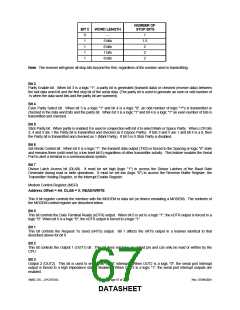
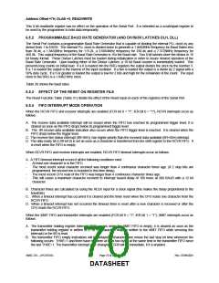
Line Control Register (LCR)
Address Offset = 3H, DLAB = 0, READ/WRITE
Start
LSB Data 5-8 bits MSB
Parity
Stop
FIGURE 1 − SERIAL DATA
This register contains the format information of the serial line. The bit definitions are:
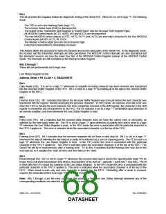
Bits 0 and 1
These two bits specify the number of bits in each transmitted or received serial character. The encoding of bits 0 and 1
is as follows:
The Start, Stop and Parity bits are not included in the word length.
BIT 1
BIT 0
WORD LENGTH
5 Bits
0
0
1
1
0
1
0
1
6 Bits
7 Bits
8 Bits
Bit 2
This bit specifies the number of stop bits in each transmitted or received serial character. The following table
summarizes the information.
SMSC DS – LPC47S45x
Page 66 of 259
Rev. 07/09/2001
DATASHEET

 SMSC [ SMSC CORPORATION ]