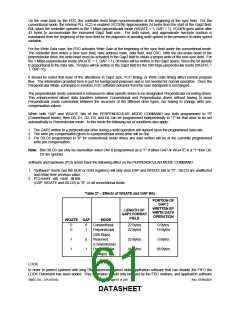
should refrain from using it. If an application calls for the FIFO to be disabled then the CONFIGURE command should
be used.
The LOCK command defines whether the EFIFO, FIFOTHR, and PRETRK parameters of the CONFIGURE command
can be RESET by the DOR and DSR registers. When the LOCK bit is set to logic "1" all subsequent "software RESETS
by the DOR and DSR registers will not change the previously set parameters to their default values. All "hardware"
RESET from the PCI_RESET# pin will set the LOCK bit to logic "0" and return the EFIFO, FIFOTHR, and PRETRK to
their default values. A status byte is returned immediately after issuing a LOCK command. This byte reflects the value
of the LOCK bit set by the command byte.
Enhanced DUMPREG
The DUMPREG command is designed to support system run-time diagnostics and application software development
and debug. To accommodate the LOCK command and the enhanced PERPENDICULAR MODE command the eighth
byte of the DUMPREG command has been modified to contain the additional data from these two commands.
Compatibility
The LPC47S45x was designed with software compatibility in mind. It is a fully backwards- compatible solution with the
older generation 765A/B disk controllers. The FDC also implements on-board registers for compatibility with the PS/2, as
well as PC/AT and PC/XT, floppy disk controller subsystems. After a PCI reset of the FDC, all registers, functions and
enhancements default to a PC/AT, PS/2 or PS/2 Model 30 compatible operating mode, depending on how the IDENT
and MFM bits are configured by the system BIOS.
6.4.9 DIRECT SUPPORT FOR TWO FLOPPY DRIVES
The MTR1# function is on pin 43. MTR1# is the second alternate function on the GP22 pin. Pin 43 has IO12 buffer
type.
The MTR1# function is selectable as open drain or push pull as MTR0# is through bit 6 of the FDD Mode Register in
CRF0 of LD 0. This overrides the selection of the output type through bit 7 of the GPIO control register. It is also
controlled by bit 7 of the FDD Mode Register.
The DS1# function is on pin 41. DS1# is the second alternate function on the GP20 pin. Pin 41 has IO12 buffer type.
The DS1# function is selectable as open drain or push pull as DS0# is through bit 6 of the FDD Mode Register in
CRF0 of LD 0. This overrides the selection of the output type through bit 7 of the GPIO control register. It is also
controlled by bit 7 of the FDD Mode register.
See the Runtime Registers section for register information.
Disk Change Support for Second Floppy
Bit[1] in the Force Disk Change register supports the second floppy. Setting either of the Force Disk Change bits
active forces the internal FDD nDSKCHG active when the appropriate drive has been selected. The Force Disk
Change register is defined in the Runtime Registers section.
Force Write Protect Support for Second Floppy
Bit[0] in the Device Disable register and FDD Option register support floppy write protect.
See the Runtime Registers section for Device Disable register description and the Configuration Registers section for
FDD Option register description.
SMSC DS – LPC47S45x
Page 62 of 259
Rev. 07/09/2001
DATASHEET

 SMSC [ SMSC CORPORATION ]