Non-DMA Mode - Transfers from the Host to the FIFO
This part does not support non-DMA mode.
DMA Mode - Transfers from the FIFO to the Host
The FDC generates a DMA request cycle when the FIFO contains (16 - <threshold>) bytes, or the last byte of a full
sector transfer has been placed in the FIFO. The DMA controller must respond to the request by reading data from the
FIFO. The FDC will deactivate the DMA request when the FIFO becomes empty by generating the proper sync for the
data transfer.
DMA Mode - Transfers from the Host to the FIFO.
The FDC generates a DMA request cycle when entering the execution phase of the data transfer commands. The DMA
controller must respond by placing data in the FIFO. The DMA request remains active until the FIFO becomes full. The
DMA request cycle is reasserted when the FIFO has <threshold> bytes remaining in the FIFO. The FDC will terminate
the DMA cycle after a TC, indicating that no more data is required.
Data Transfer Termination
The FDC supports terminal count explicitly through the TC cycle and implicitly through the underrun/overrun and end-of-
track (EOT) functions. For full sector transfers, the EOT parameter can define the last sector to be transferred in a
single or multi-sector transfer.
If the last sector to be transferred is a partial sector, the host can stop transferring the data in mid-sector, and the FDC
will continue to complete the sector as if a TC cycle was received. The only difference between these implicit functions
and TC cycle is that they return "abnormal termination" result status. Such status indications can be ignored if they were
expected.
Note: when the host is sending data to the FIFO of the FDC, the internal sector count will be complete when the FDC
reads the last byte from its side of the FIFO. There may be a delay in the removal of the transfer request signal of up
to the time taken for the FDC to read the last 16 bytes from the FIFO. The host must tolerate this delay.
Result Phase
The generation of the interrupt determines the beginning of the result phase. For each of the commands, a defined set
of result bytes has to be read from the FDC before the result phase is complete. These bytes of data must be read out
for another command to start.
RQM and DIO must both equal "1" before the result bytes may be read. After all the result bytes have been read, the
RQM and DIO bits switch to "1" and "0" respectively, and the CB bit is cleared, indicating that the FDC is ready to accept
the next command.
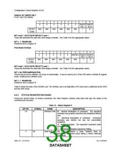
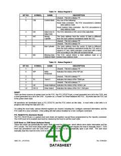
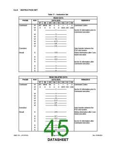
6.4.5 COMMAND SET/DESCRIPTIONS
Commands can be written whenever the FDC is in the command phase. Each command has a unique set of needed
parameters and status results. The FDC checks to see that the first byte is a valid command and, if valid, proceeds
with the command. If it is invalid, an interrupt is issued. The user sends a Sense Interrupt Status command which
returns an invalid command error. Refer to Table 16 for explanations of the various symbols used. Table 17 lists the
required parameters and the results associated with each command that the FDC is capable of performing.
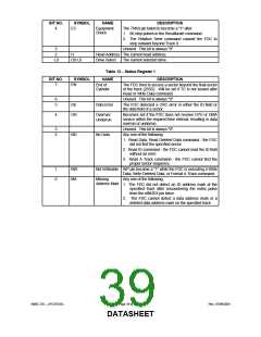
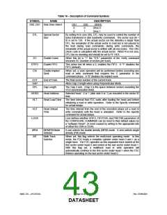
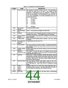
Table 16 − Description of Command Symbols
SYMBOL
NAME
DESCRIPTION
C
D
Cylinder Address The currently selected address; 0 to 255.
Data Pattern
The pattern to be written in each sector data field during formatting.
D0, D1
Drive Select 0-1
Designates which drives are perpendicular drives on the
Perpendicular Mode Command. A "1" indicates a perpendicular
drive.
DIR
Direction Control
If this bit is 0, then the head will step out from the spindle during a
relative seek. If set to a 1, the head will step in toward the spindle.
SMSC DS – LPC47S45x
Page 42 of 259
Rev. 07/09/2001
DATASHEET

 SMSC [ SMSC CORPORATION ]