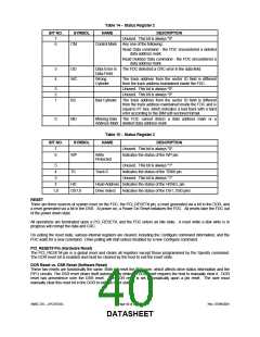
MODES OF OPERATION
The FDC has three modes of operation, PC/AT mode, PS/2 mode and Model 30 mode. These are determined by the
state of the Interface Mode bits in LD0-CRF0[3,2].
PC/AT mode
The PC/AT register set is enabled, the DMA enable bit of the DOR becomes valid (controls the interrupt and DMA
functions), and DENSEL is an active high signal.
PS/2 mode
This mode supports the PS/2 models 50/60/80 configuration and register set. The DMA bit of the DOR becomes a
"don't care". The DMA and interrupt functions are always enabled, and DENSEL is an active low.
Model 30 mode
This mode supports PS/2 Model 30 configuration and register set. The DMA enable bit of the DOR becomes valid
(controls the interrupt and DMA functions), and DENSEL is active low.
6.4.3 DMA TRANSFERS
DMA transfers are enabled with the Specify command and are initiated by the FDC by activating a DMA request cycle.
DMA read, write and verify cycles are supported. The FDC supports two DMA transfer modes: single Transfer and
Burst Transfer. Burst mode is enabled via Logical Device 0-CRF0-Bit[1] (LD0-CRF0[1]).
6.4.4 CONTROLLER PHASES
For simplicity, command handling in the FDC can be divided into three phases: Command, Execution, and Result. Each
phase is described in the following sections.
Command Phase
After a reset, the FDC enters the command phase and is ready to accept a command from the host. For each of the
commands, a defined set of command code bytes and parameter bytes has to be written to the FDC before the
command phase is complete. (Please refer to Table 16 for the command set descriptions). These bytes of data must be
transferred in the order prescribed.
Before writing to the FDC, the host must examine the RQM and DIO bits of the Main Status Register. RQM and DIO
must be equal to "1" and "0" respectively before command bytes may be written. RQM is set false by the FDC after
each write cycle until the received byte is processed. The FDC asserts RQM again to request each parameter byte of
the command unless an illegal command condition is detected. After the last parameter byte is received, RQM remains
"0" and the FDC automatically enters the next phase as defined by the command definition.
The FIFO is disabled during the command phase to provide for the proper handling of the "Invalid Command" condition.
Execution Phase
All data transfers to or from the FDC occur during the execution phase, which can proceed in DMA mode as indicated in
the Specify command.
After a reset, the FIFO is disabled. Each data byte is transferred by an read/write or DMA cycle depending on the
DMA mode. The Configure command can enable the FIFO and set the FIFO threshold value.
The following paragraphs detail the operation of the FIFO flow control. In these descriptions, <threshold> is defined as
the number of bytes available to the FDC when service is requested from the host and ranges from 1 to 16. The
parameter FIFOTHR, which the user programs, is one less and ranges from 0 to 15.
A low threshold value (i.e. 2) results in longer periods of time between service requests, but requires faster servicing of
the request for both read and write cases. The host reads (writes) from (to) the FIFO until empty (full), then the transfer
request goes inactive. The host must be very responsive to the service request. This is the desired case for use with a
"fast" system.
A high value of threshold (i.e. 12) is used with a "sluggish" system by affording a long latency period after a service
request, but results in more frequent service requests.
Non-DMA Mode - Transfers from the FIFO to the Host
This part does not support non-DMA mode.
SMSC DS – LPC47S45x
Page 41 of 259
Rev. 07/09/2001
DATASHEET

 SMSC [ SMSC CORPORATION ]