6.11 SERIAL IRQ
The LPC47M14x supports the serial interrupt to transmit interrupt information to the host system. The serial interrupt
scheme adheres to the Serial IRQ Specification for PCI Systems, Version 6.0.
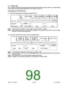
Timing Diagrams For SER_IRQ Cycle
A) Start Frame timing with source sampled a low pulse on IRQ1
START FRAME
IRQ0 FRAME IRQ1 FRAME IRQ2 FRAME
SL
or
H
R
T
S
R
T
S
R
T
S
R
T
H
PCI_CLK
1
START
SER_IRQ
Drive Source
IRQ1
Host Controller
None
IRQ1
None
Note: H=Host Control; R=Recovery; T=Turn-Around; SL=Slave Control; S=Sample
Note 1: Start Frame pulse can be 4-8 clocks wide depending on the location of the device in the PCI bridge
hierarchy in a synchronous bridge design.
B) Stop Frame Timing with Host using 17 SER_IRQ sampling period
IRQ14
IRQ15
IOCHCK#
FRAME
STOP FRAME
NEXT CYCLE
FRAME
FRAME
I 2
S
R
T
S
R
T
S
R
T
H
R
T
PCI_CLK
SER_IRQ
1
3
STOP
START
None
IRQ15
None
Host Controller
Driver
Note: H=Host Control; R=Recovery; T=Turn-Around; S=Sample; I=Idle
Note 1: The next SER_IRQ cycle’s Start Frame pulse may or may not start immediately after the turn-around clock
of the Stop Frame.
Note 2: There may be none, one or more Idle states during the Stop Frame.
Note 3: Stop pulse is 2 clocks wide for Quiet mode, 3 clocks wide for Continuous mode.
SMSC DS – LPC47M14X
Page 98
Rev. 03/19/2001

 SMSC [ SMSC CORPORATION ]