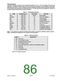
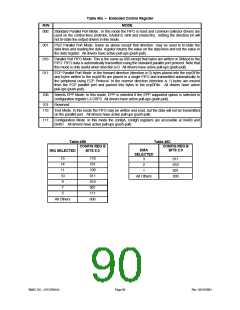
Register Definitions
The register definitions are based on the standard IBM addresses for LPT. All of the standard printer ports are
supported. The additional registers attach to an upper bit decode of the standard LPT port definition to avoid conflict
with standard ISA devices. The port is equivalent to a generic parallel port interface and may be operated in that mode.
The port registers vary depending on the mode field in the ecr. The table below lists these dependencies. Operation of
the devices in modes other that those specified is undefined.
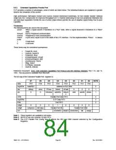
Table 43 – ECP Register Definitions
NAME
ADDRESS (Note 1)
+000h R/W
+000h R/W
+001h R/W
+002h R/W
+400h R/W
+400h R/W
+400h R/W
+400h R
ECP MODES
FUNCTION
Data Register
ECP FIFO (Address)
Status Register
data
000-001
011
All
ecpAFifo
dsr
dcr
All
Control Register
cFifo
ecpDFifo
tFifo
cnfgA
cnfgB
ecr
010
011
110
111
111
All
Parallel Port Data FIFO
ECP FIFO (DATA)
Test FIFO
Configuration Register A
Configuration Register B
Extended Control Register
+401h R/W
+402h R/W
Note 1: These addresses are added to the parallel port base address as selected by configuration register or jumpers.
Note 2: All addresses are qualified with AEN. Refer to the AEN pin definition.
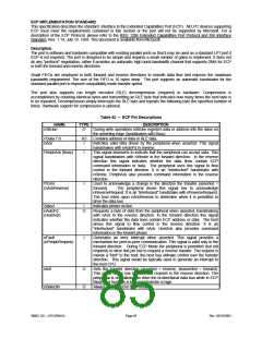
Table 44 – Mode Descriptions
MODE
000
001
010
011
100
101
110
111
DESCRIPTION*
SPP mode
PS/2 Parallel Port mode
Parallel Port Data FIFO mode
ECP Parallel Port mode
EPP mode (If this option is enabled in the configuration registers)
Reserved
Test mode
Configuration mode
*Refer to ECR Register Description
SMSC DS – LPC47M14X
Page 86
Rev. 03/19/2001

 SMSC [ SMSC CORPORATION ]