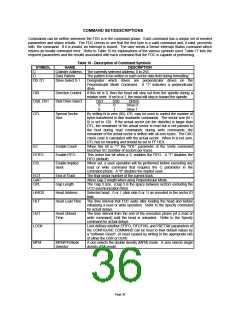
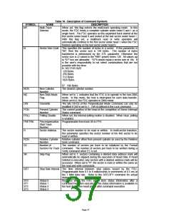
Table 16 - Description of Command Symbols
SYMBOL
MT
NAME
Multi-Track
Selector
DESCRIPTION
When set, this flag selects the multi-track operating mode. In this
mode, the FDC treats a complete cylinder under head 0 and 1 as a
single track. The FDC operates as this expanded track started at the
first sector under head 0 and ended at the last sector under head 1.
With this flag set, a multitrack read or write operation will
automatically continue to the first sector under head 1 when the FDC
finishes operating on the last sector under head 0.
N
Sector Size Code This specifies the number of bytes in a sector. If this parameter is
"00", then the sector size is 128 bytes. The number of bytes
transferred is determined by the DTL parameter. Otherwise the
sector size is (2 raised to the "N'th" power) times 128. All values up
to "07" hex are allowable. "07"h would equal a sector size of 16k. It
is the user's responsibility to not select combinations that are not
possible with the drive.
N SECTOR SIZE
128 Bytes
256 Bytes
512 Bytes
1024 Bytes
…
…
07 16K Bytes
NCN
ND
New Cylinder
Number
Non-DMA Mode
Flag
The desired cylinder number.
When set to 1, indicates that the FDC is to operate in the non-DMA
mode. In this mode, the host is interrupted for each data transfer.
When set to 0, the FDC operates in DMA mode.
OW
Overwrite
The bits D0-D3 of the Perpendicular Mode Command can only be
modified if OW is set to 1. OW id defined in the Lock command.
The current position of the head at the completion of Sense Interrupt
Status command.
PCN
Present Cylinder
Number
POLL
PRETRK
Polling Disable
When set, the internal polling routine is disabled. When clear, polling
is enabled.
Precompensation Programmable from track 00 to FFH.
Start Track
Number
R
Sector Address
The sector number to be read or written. In multi-sector transfers,
this parameter specifies the sector number of the first sector to be
read or written.
RCN
SC
Relative Cylinder
Number
Number of
Relative cylinder offset from present cylinder as used by the Relative
Seek command.
The number of sectors per track to be initialized by the Format
Sectors Per Track command. The number of sectors per track to be verified during a
Verify command when EC is set.
SK
Skip Flag
When set to 1, sectors containing a deleted data address mark will
automatically be skipped during the execution of Read Data. If Read
Deleted is executed, only sectors with a deleted address mark will be
accessed. When set to "0", the sector is read or written the same as
the read and write commands.
SRT
Step Rate Interval The time interval between step pulses issued by the FDC.
Programmable from 0.5 to 8 milliseconds in increments of 0.5 ms at
the 1 Mbit data rate. Refer to the SPECIFY command for actual
delays.
ST0
ST1
ST2
ST3
Status 0
Status 1
Status 2
Status 3
Registers within the FDC which store status information after a
command has been executed. This status information is available to
the host during the result phase after command execution.
Page 37

 SMSC [ SMSC CORPORATION ]