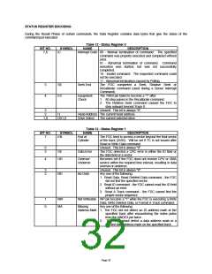
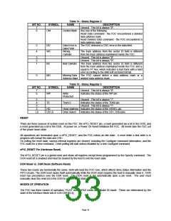
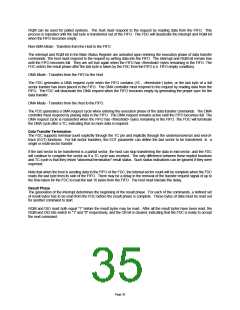
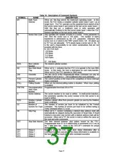
COMMAND SET/DESCRIPTIONS
Commands can be written whenever the FDC is in the command phase. Each command has a unique set of needed
parameters and status results. The FDC checks to see that the first byte is a valid command and, if valid, proceeds
with the command. If it is invalid, an interrupt is issued. The user sends a Sense Interrupt Status command which
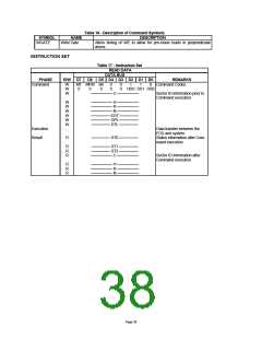
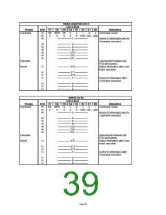
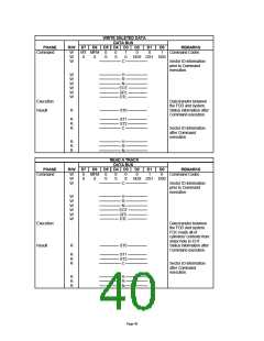
returns an invalid command error. Refer to Table 16 for explanations of the various symbols used. Table 17 lists the
required parameters and the results associated with each command that the FDC is capable of performing.
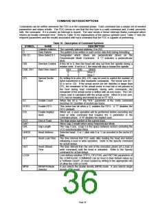
Table 16 - Description of Command Symbols
SYMBOL
NAME
DESCRIPTION
C
Cylinder Address The currently selected address; 0 to 255.
D
Data Pattern
The pattern to be written in each sector data field during formatting.
D0, D1
Drive Select 0-1
Designates which drives are perpendicular drives on the
Perpendicular Mode Command. A "1" indicates a perpendicular
drive.
DIR
Direction Control
Disk Drive Select
If this bit is 0, then the head will step out from the spindle during a
relative seek. If set to a 1, the head will step in toward the spindle.
DS0, DS1
DS1
0
DS0
0
DRIVE
Drive 0
Drive 1
0
1
DTL
Special Sector
Size
By setting N to zero (00), DTL may be used to control the number of
bytes transferred in disk read/write commands. The sector size (N =
0) is set to 128. If the actual sector (on the diskette) is larger than
DTL, the remainder of the actual sector is read but is not passed to
the host during read commands; during write commands, the
remainder of the actual sector is written with all zero bytes. The CRC
check code is calculated with the actual sector. When N is not zero,
DTL has no meaning and should be set to FF HEX.
When this bit is "1" the "DTL" parameter of the Verify command
becomes SC (number of sectors per track).
This active low bit when a 0, enables the FIFO. A "1" disables the
FIFO (default).
When set, a seek operation will be performed before executing any
read or write command that requires the C parameter in the
command phase. A "0" disables the implied seek.
EC
Enable Count
Enable FIFO
EFIFO
EIS
Enable Implied
Seek
EOT
GAP
GPL
End of Track
Gap Length
The final sector number of the current track.
Alters Gap 2 length when using Perpendicular Mode.
The Gap 3 size. (Gap 3 is the space between sectors excluding the
VCO synchronization field).
H/HDS
HLT
Head Address
Head Load Time
Selected head: 0 or 1 (disk side 0 or 1) as encoded in the sector ID
field.
The time interval that FDC waits after loading the head and before
initializing a read or write operation. Refer to the Specify command
for actual delays.
HUT
Head Unload
Time
The time interval from the end of the execution phase (of a read or
write command) until the head is unloaded. Refer to the Specify
command for actual delays.
LOCK
Lock defines whether EFIFO, FIFOTHR, and PRETRK parameters of
the CONFIGURE COMMAND can be reset to their default values by
a "software Reset". (A reset caused by writing to the appropriate bits
of either the DSR or DOR)
MFM
MFM/FM Mode
Selector
A one selects the double density (MFM) mode. A zero selects single
density (FM) mode.
Page 36

 SMSC [ SMSC CORPORATION ]