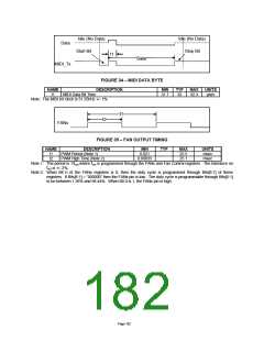
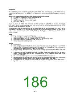
Idle (No Data)
Start Bit
Idle (No Data)
Stop Bit
Data
t1
Data
MIDI_Tx
FIGURE 34 – MIDI DATA BYTE
NAME
t1
DESCRIPTION
MIN
31.7
TYP
32
MAX
32.3
UNITS
µsec
MIDI Data Bit Time
Note: The MIDI bit clock is 31.25kHz +/- 1%
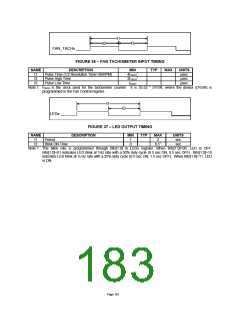
t1
t2
FANx
FIGURE 35 – FAN OUTPUT TIMING
NAME
t1
t2
DESCRIPTION
PWM Period (Note 1)
PWM High Time (Note 2)
MIN
0.021
0.00033
TYP
MAX
25.5
25.1
UNITS
msec
msec
Note 1: The period is 1/fout,where fout is programmed through the FANx and Fan Control registers. The tolerance on
out is +/- 2%.
f
Note 2: When Bit 0 of the FANx registers is 0, then the duty cycle is programmed through Bits[6:1] of these
registers. If Bits[6:1] = “000000” then the FANx pin is low. The duty cycle is programmable through Bits[6:1]
to be between 1.56% and 98.44%. When Bit 0 is 1, the FANx pin is high.
Page 182

 SMSC [ SMSC CORPORATION ]