INTERRUPT IDENTIFICATION REGISTER (IIR)
Address Offset = 2H, DLAB = X, READ
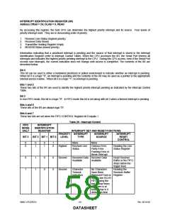
By accessing this register, the host CPU can determine the highest priority interrupt and its source. Four levels of
priority interrupt exist. They are in descending order of priority:
1. Receiver Line Status (highest priority)
2. Received Data Ready
3. Transmitter Holding Register Empty
4. MODEM Status (lowest priority)
Information indicating that a prioritized interrupt is pending and the source of that interrupt is stored in the Interrupt
Identification Register (refer to Interrupt Control Table). When the CPU accesses the IIR, the Serial Port freezes all
interrupts and indicates the highest priority pending interrupt to the CPU. During this CPU access, even if the Serial Port
records new interrupts, the current indication does not change until access is completed. The contents of the IIR are
described below.
Bit 0
This bit can be used in either a hardwired prioritized or polled environment to indicate whether an interrupt is pending.
When bit 0 is a logic "0", an interrupt is pending and the contents of the IIR may be used as a pointer to the appropriate
internal service routine. When bit 0 is a logic "1", no interrupt is pending.
Bits 1 and 2
These two bits of the IIR are used to identify the highest priority interrupt pending as indicated by the Interrupt Control
Table.
Bit 3
In non-FIFO mode, this bit is a logic "0". In FIFO mode this bit is set along with bit 2 when a timeout interrupt is pending.
Bits 4 and 5
These bits of the IIR are always logic "0".
Bits 6 and 7
These two bits are set when the FIFO CONTROL Register bit 0 equals 1.
Table 29 - Interrupt Control
FIFO
MODE
ONLY
INTERRUPT
IDENTIFICATION
REGISTER
INTERRUPT SET AND RESET FUNCTIONS
PRIORITY INTERRUPT
INTERRUPT
SOURCE
INTERRUPT
BIT 3
BIT 2 BIT 1 BIT 0
LEVEL
TYPE
RESET
CONTROL
-
0
0
0
1
0
1
1
0
-
None
None
Highest
Receiver Line
Status
Overrun Error,
Parity Error,
Reading the Line
Status Register
Framing Error or
Break Interrupt
0
1
1
1
0
0
0
0
Second
Second
Received Data Receiver Data
Read Receiver
Buffer or the FIFO
drops below the
trigger level.
Available
Available
Character
Timeout
No Characters
Have Been
Reading the
Receiver Buffer
Indication
Removed From or Register
Input to the RCVR
FIFO during the
last 4 Char times
and there is at
least 1 char in it
during this time
SMSC LPC47B27x
- 58 -
Rev. 08-10-04
DATASHEET

 SMSC [ SMSC CORPORATION ]