Three Port 10/100 Managed Ethernet Switch with MII
Datasheet
The I2C slave controller implements the low level I2C slave serial interface (start and stop condition
detection, data bit transmission/reception, and acknowledge generation/reception), handles the slave
command protocol, and performs system register reads and writes. The I2C slave controller conforms
to the Philips I2C-Bus Specification.
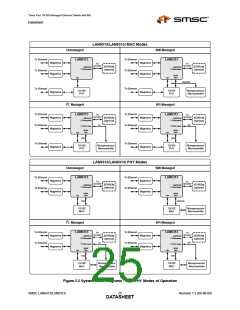
A list of management modes and configurations settings for these modes is discussed in Section 2.3,
"Modes of Operation"
2.2.7
SMI Slave Controller
This module provides a SMI slave interface which can be used for CPU management of the
LAN9313/LAN9313i via the MII pins, and allows CPU access to all system CSRs. SMI uses the same
pins and protocol of the IEEE MII management function, and differs only in that SMI provides access
to all internal registers by using a non-standard extended addressing map. The SMI protocol co-exists
with the MII management protocol by using the upper half of the PHY address space (16 through 31).
A list of management modes and configurations settings for these modes is discussed in Section 2.3,
"Modes of Operation"
2.2.8
EEPROM Controller/Loader
The EEPROM Controller is an I2C/Microwire master module which interfaces an optional external
EEPROM with the system register bus and the EEPROM Loader. Multiple types (I2C/Microwire) and
sizes of external EEPROMs are supported. Configuration of the EEPROM type and size are
accomplished via the eeprom_type_strap and eeprom_size_strap[1:0] configuration straps respectively.
Various commands are supported for each EEPROM type, allowing for the storage and retrieval of
static data. The I2C interface conforms to the Philips I2C-Bus Specification.
The EEPROM Loader module interfaces to the EEPROM Controller, Ethernet PHYs, and the system
CSRs. The EEPROM Loader provides the automatic loading of configuration settings from the
EEPROM into the LAN9313/LAN9313i at reset, allowing the LAN9313/LAN9313i to operate
unmanaged. The EEPROM Loader runs upon a pin reset (nRST), power-on reset (POR), digital reset
(DIGITAL_RST bit in the Reset Control Register (RESET_CTL)), or upon the issuance of a RELOAD
command via the EEPROM Command Register (E2P_CMD).
2.2.9
1588 Time Stamp
The IEEE 1588 Time Stamp modules provide hardware support for the IEEE 1588 Precision Time
Protocol (PTP), allowing clock synchronization with remote Ethernet devices, packet time stamping,
and time driven event generation. Time stamping is supported on all ports, with an individual IEEE
1588 Time Stamp module connected to each port via the MII bus. Any port may function as a master
or a slave clock per the IEEE 1588 specification, and the LAN9313/LAN9313i as a whole may function
as a boundary clock.
A 64-bit tunable clock is provided that is used as the time source for all IEEE 1588 time stamp related
functions. The IEEE 1588 Clock/Events block provides IEEE 1588 clock comparison based interrupt
generation and time stamp related GPIO event generation. Two LAN9313/LAN9313i GPIO pins
(GPIO[8:9]) can be used to trigger a time stamp capture when configured as an input, or output a
signal from the GPIO based on an IEEE 1588 clock target compare event when configured as an
output. All features of the IEEE 1588 hardware time stamp unit can be monitored and configured via
their respective IEEE 1588 configuration and status registers (CSRs).
2.2.10
GPIO/LED Controller
The LAN9313/LAN9313i provides 12 configurable general-purpose input/output pins which are
controlled via this module. These pins can be individually configured via the GPIO/LED CSRs to
function as inputs, push-pull outputs, or open drain outputs and each is capable of interrupt generation
with configurable polarity. Two of the GPIO pins (GPIO[9:8]) can be used for IEEE 1588 timestamp
functions, allowing GPIO driven 1588 time clock capture when configured as an input, or GPIO output
generation based on an IEEE 1588 clock target compare event.
Revision 1.2 (04-08-08)
SMSC LAN9313/LAN9313i
DATA2S2HEET

 SMSC [ SMSC CORPORATION ]