Three Port 10/100 Managed Ethernet Switch with MII
Datasheet
10.2
IEEE 1588 Time Stamp
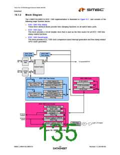
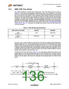
The LAN9313/LAN9313i contains three identical IEEE 1588 Time Stamp blocks as shown in
Figure 10.1. These blocks are responsible for capturing the source UUID, sequence ID, and current
64-bit IEEE 1588 clock time upon detection of a Sync or Delay_Req message type on their respective
port. The mode of the clock (master or slave) determines which message is detected on receive and
transmit. For slave clock operation, Sync messages are detected on receive and Delay_Req messages
on transmit. For master clock operation, Delay_Req messages are detected on receive and Sync
messages on transmit. Follow_Up, Delay_Resp and Management packet types do not cause capture.
Each port may be individually configured as an IEEE 1588 master or slave clock via the master/slave
bits (M_nS_1 for Port 1, MnS_2 for Port2, and M_nS_MII for Port 0) in the 1588 Configuration Register
(1588_CONFIG). Table 10.1 summarizes the message type detection under slave and master IEEE
1588 clock operation.
Table 10.1 IEEE 1588 Message Type Detection
IEEE 1588 CLOCK MODE
RECEIVE
TRANSMIT
Slave
Sync
Delay_Req
(M_nS_x = 0)
Master
Delay_Req
Sync
(M_nS_x = 1)
For ports 1 and 2, receive is defined as data from the PHY (from the outside world) and transmit is
defined as data to the PHY. This is consistent with the point-of-view of where the partner clock resides
(LAN9313/LAN9313i receives packets from the partner via the PHY, etc.). For the time stamp module
connected to the external MII port (Port 0), the definition of transmit and receive is reversed. Receive
is defined as data from the switch fabric, while transmit is defined as data to the switch fabric. This is
consistent with the point-of-view of where the partner clock resides (LAN9313/LAN9313i receives
packets from the partner via the switch fabric, etc.).
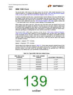
As defined by IEEE 1588, and shown in Figure 10.2, the message time stamp point is defined as the
leading edge of the first data bit following the Start of Frame Delimiter (SFD). However, since the
packet contents are not yet known, the time stamp can not yet be loaded into the capture register.
Therefore, the time stamp is first stored into a temporary internal holding register at the start of every
packet.
Message Timestamp
Point
Ethernet
Start of Frame
Delimiter
First Octet
following
Start of Frame
Preamble
Octet
1
0
1
1
1
1
1 1 1
0
0
0
0
0
0 0 0 0 0 0 0
bit time
Figure 10.2 IEEE 1588 Message Time Stamp Point
Revision 1.2 (04-08-08)
136
SMSC LAN9313/LAN9313i
DATASHEET

 SMSC [ SMSC CORPORATION ]