Three Port 10/100 Managed Ethernet Switch with MII
Datasheet
8.2.3
Microwire EEPROM
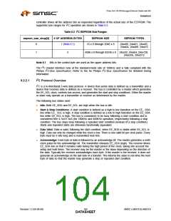
Based on the configuration strap eeprom_type_strap, various sized Microwire EEPROMs are
supported. The varying size ranges are supported by additional bits in the address field
(EPC_ADDRESS) of the EEPROM Command Register (E2P_CMD). Within each size range, the
largest EEPROM uses all the address bits, while the smaller EEPROMs treat the upper address bits
as don’t cares. The EEPROM controller drives all the address bits as requested regardless of the
actual size of the EEPROM. The supported size ranges for Microwire operation are shown in Table 8.3.
Table 8.3 Microwire EEPROM Size Ranges
eeprom_size_strap[1:0]
# OF ADDRESS BITS
EEPROM SIZE
EEPROM TYPES
00
01
10
11
7
9
128 x 8
93xx46A
256 x 8 and 512 x 8
1024 x 8 and 2048 x 8
RESERVED
93xx56A, 93xx66A
93xx76A, 93xx86A
11
Refer to Section 14.5.4, "Microwire Timing," on page 392 for detailed Microwire timing information.
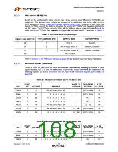
8.2.3.1
Microwire Master Commands
Table 8.4, Table 8.5, and Table 8.6 detail the Microwire command set, including the number of clock
cycles required, for 7, 9, and 11 address bits respectively. These commands are detailed in the
following sections as well as in Section 13.1.3.1, "EEPROM Command Register (E2P_CMD)," on
page 160.
Table 8.4 Microwire Command Set for 7 Address Bits
START
BIT
DATA TO
EEPROM
DATA FROM
EEPROM
# OF
CLOCKS
INST
OPCODE
ADDRESS
ERASE
ERAL
1
1
1
1
1
1
1
11
00
00
00
10
01
00
A6 A5 A4 A3 A2 A1 A0
-
(RDY/~BSY)
(RDY/~BSY)
Hi-Z
10
10
10
10
18
18
18
1
0
1
0
0
1
X
X
X
X
X
X
X
X
X
X
X
X
X
X
X
-
EWDS
EWEN
READ
WRITE
WRAL
-
-
Hi-Z
A6 A5 A4 A3 A2 A1 A0
A6 A5 A4 A3 A2 A1 A0
-
D7 - D0
D7 - D0
D7 - D0
(RDY/~BSY)
(RDY/~BSY)
0
1 X X X X X
Table 8.5 Microwire Command Set for 9 Address Bits
DATA TO
START
BIT
DATA FROM
EEPROM
# OF
CLOCKS
INST
OPCODE
ADDRESS
EEPROM
ERASE
ERAL
1
1
1
11
00
00
A8 A7 A6 A5 A4 A3 A2 A1 A0
-
-
-
(RDY/~BSY)
(RDY/~BSY)
Hi-Z
12
12
12
1
0
0
0
X
X
X
X
X
X
X
X
X
X
X
X
X
X
EWDS
Revision 1.2 (04-08-08)
108
SMSC LAN9313/LAN9313i
DATASHEET

 SMSC [ SMSC CORPORATION ]