16-bit High-Performance Single-Chip 10/100 Ethernet Controller with HP Auto-MDIX
Datasheet
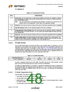
Additionally, The LAN9217 has specific rules regarding the use of transmit buffers when in Store-and-
Forward mode (i.e., HW_CFG[SF] = 1). When this mode is enabled, the total space consumed in the
TX FIFO (MIL) must be limited to no more than 2KB - 3 DWORDs (2,036 bytes total). Any transmit
packet that is so highly fragmented that it takes more space than this must be un-fragmented (by
copying to a Driver-supplied buffer) before the transmit packet can be sent to the LAN9217.
One approach to determine whether a packet is too fragmented is to calculate the actual amount of
space that it will consume, and check it against 2,036 bytes. Another approach is to check the number
of buffers against a worst-case limit of 86 (see explanation below).
3.14.3.2
Calculating Worst-Case TX FIFO (MIL) Usage
The actual space consumed by a buffer consists only of any partial DWORD offsets in the first/last
DWORD of the buffer, plus all of the whole DWORDs in between. Any whole DWORD offsets and/or
alignments are stripped off before the buffer even gets into the TX data FIFO, and TX command words
are stripped off before the buffer is written to the TX FIFO, so none of those DWORDs count as space
consumed. The worst-case overhead for a TX buffer is 6 bytes, which assumes that it started on the
high byte of a DWORD and ended on the low byte of a DWORD. A TX packet consisting of 86 such
fragments would have an overhead of 516 bytes (6 * 86) which, when added to a 1514-byte max-size
transmit packet (1516 bytes, rounded up to the next whole DWORD), would give a total space
consumption of 2,032 bytes, leaving 4 bytes to spare; this is the basis for the "86 fragment" rule
mentioned above.
3.14.4
TX Status Format
TX status is passed to the host CPU through a separate FIFO mechanism. A status word is returned
for each packet transmitted. Data transmission is suspended if the TX status FIFO becomes full. Data
transmission will resume when the host reads the TX status and there is room in the FIFO for more
“TX Status” data.
The host can optionally choose to not read the TX status. The host can optionally ignore the TX status
by setting the “TX Status Discard Allow Overrun Enable” (TXSAO) bit in the TX Configuration Register
(TX_CFG). If this option is chosen TX status will not be written to the FIFO. Setting this bit high allows
the transmitter to continue operation with a full TX status FIFO. In this mode the status information is
still available in the TX status FIFO, and TX status interrupts still function. In the case of an overrun,
the TXSUSED counter will stay at zero and no further TX status will be written to the TX status FIFO
until the host frees space by reading TX status. If TXSAO is enabled, a TXE error will not be generated
if the TX status FIFO overruns. In this mode the host is responsible for re-synchronizing TX status in
the case of an overrun.
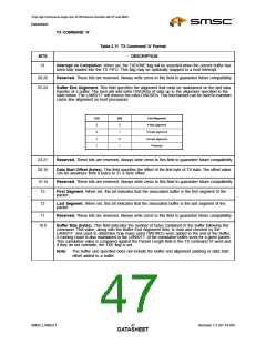
BITS
DESCRIPTION
31:16
Packet TAG. Unique identifier written by the host into the Packet Tag field of the TX command ‘B’
word. This field can be used by the host to correlate TX status words with the associated TX packets.
15
Error Status (ES). ). When set, this bit indicates that the Ethernet controller has reported an error.
This bit is the logical OR of bits 11, 10, 9, 8, 2, 1 in this status word.
14:12
11
Reserved. These bits are reserved. Always write zeros to this field to guarantee future compatibility.
Loss of Carrier. When set, this bit indicates the loss of carrier during transmission.
10
No Carrier. When set, this bit indicates that the carrier signal from the transceiver was not present
during transmission.
9
8
Late Collision. When set, indicates that the packet transmission was aborted after the collision
window of 64 bytes.
Excessive Collisions. When set, this bit indicates that the transmission was aborted after 16
collisions while attempting to transmit the current packet.
SMSC LAN9217
Revision 1.5 (07-18-06)
DATA4S9HEET

 SMSC [ SMSC CORPORATION ]