High Performance Two Port 10/100 Managed Ethernet Switch with 32-Bit Non-PCI CPU Interface
Datasheet
7.2
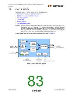
Port 1 & 2 PHYs
Functionally, each PHY can be divided into the following sections:
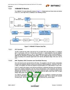
100BASE-TX Transmit and 100BASE-TX Receive
10BASE-T Transmit and 10BASE-T Receive
PHY Auto-negotiation
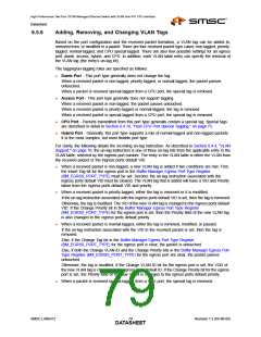
HP Auto-MDIX
MII MAC Interface
PHY Management Control
Note 7.1 Because the Port 1 PHY and Port 2 PHY are functionally identical, this section will describe
them as the “Port x PHY”, or simply “PHY”. Wherever a lowercase “x” has been appended
to a port or signal name, it can be replaced with “1” or “2” to indicate the Port 1 or Port 2
PHY respectively. All references to “PHY” in this section can be used interchangeably for
both the Port 1 & 2 PHYs. This nomenclature excludes the Virtual PHY.
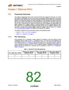
A block diagram of the Port x PHYs main components can be seen in Figure 7.1.
Auto-
Negotiation
10/100
Transmitter
TXPx/TXNx
MII
MAC
Interface
MII
To External
Port x Ethernet Pins
HP Auto-MDIX
To Port x
RXPx/RXNx
Switch Fabric MAC
10/100
Reciever
PHY Management
Control
MDIO
To Host MAC
LEDs
PLL
Registers
Interrupts
To System
Interrupt Controller
To GPIO/LED
Controller
From
System Clocks Controller
Figure 7.1 Port x PHY Block Diagram
SMSC LAN9312
Revision 1.2 (04-08-08)
DATA8S3HEET

 SMSC [ SMSC CORPORATION ]