Non-PCI Single-Chip Full Duplex Ethernet Controller with Magic Packet
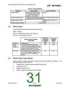
Table 5.5 - Interrupt Merging
FUNCTION
Interrupt Output
PCMCIA MODE
LOCAL BUS MODE
INTR0-3
nIREQ when function is Ready.
Acts as ready line at power up.
I.e. remains low until the chip
(therefore, card) is Ready
Ethernet Interrupt Source
Ethernet Interrupt Enable
Ethernet Interrupt Status Bit
OR function of all interrupt bits specified in the Interrupt Status Register
ANDed with their respective Enable bits
Not Applicable in LOCAL BUS
mode
Intr bit in ECSR
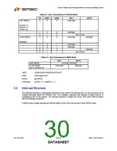
5.3
Reset Logic
The pins and bits involved in the different reset mechanisms are:
RESET - Input Pin
SRESET - Soft Reset bit in ECOR, or the SRESET bit
SOFT RST - EPH Soft Reset bit in RCR
SAMPLES
TRIGGERS
EEPROM
READ
RESETS THE FOLLOWING
FUNCTIONS
LOCAL BUS
VS. PCMCIA
MODE
RESET pin
All internal logic
Yes
No
Yes
Yes
ECOR
The Ethernet controller function and
Register
SRESET bit
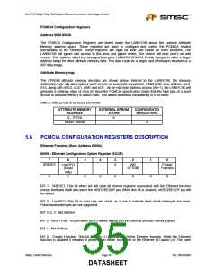
Ethernet PCMCIA Configuration Registers
except for the bit itself. Setting this bit also
lowers the nIREQ/READY line. When
cleared, the nIREQ/READY line is raised.
SOFT RST
The Ethernet controller itself except for
the IA, CONF and BASE registers. It does
not reset any PCMCIA Configuration
Register.
No
No
5.4
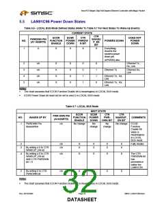
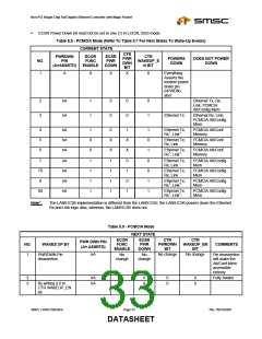
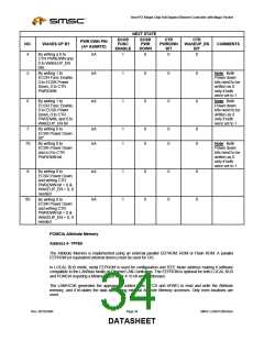
Power Down Logic States
Table 5.6, Table 5.7, Table 5.8, and Table 5.9 describe the power down states of the LAN91C96. The
pins and bits involved in power down are:
1.
2.
3.
4.
PWRDWN/TXCLK - Input pin valid when XENDEC is not zero (0).
Pwrdwn bits in ECSR
Enable Function bit in ECOR
PWRDN - Legacy power down bit in Control Register.
SMSC LAN91C965v&3v
Page 31
Rev. 09/10/2004
DATASHEET

 SMSC [ SMSC CORPORATION ]