Non-PCI Single-Chip Full Duplex Ethernet Controller with Magic Packet
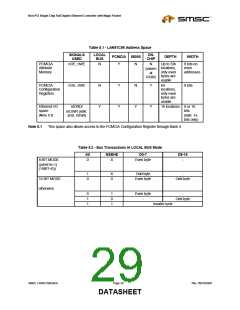
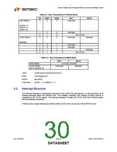
Table 5.3 - Bus Transactions In PCMCIA Mode
A0
0
NCE1
0
NCE2
X
D0-7
Even byte
D8-15
8 BIT MODE
-
((IOis8=1) +
(nEN16=1).
(16BIT=0))
1
X
0
0
1
0
X
X
0
Odd byte
Even byte
-
NO CYCLE
16 BIT MODE
otherwise
Odd byte
0
1
X
0
0
1
1
1
1
0
1
Even byte
Odd byte
-
-
Odd byte
X
NO CYCLE
Table 5.4 - Bus Transactions In 68000 Mode
D0-7
D8-15
8 BIT MODE
16 BIT MODE
ILLEGAL ACCESS
Even byte Odd byte
(A0=0).(nSBHE=0)
16BIT:
CONFIGURATION REGISTER bit 7
CSR register bit 5
IOis8:
nEN16:
8 Bit mode:
pin nEN16
((IOis8 = 1) + (nMIS16 = 1)
5.2
Interrupt Structure
The Ethernet interrupt is conceptually equivalent to the LAN91C94 interrupt line, it is the or function of all
enabled interrupts within the Ethernet core. The enabling, reporting, and clearing of these sources is
controlled by the ECOR register. The interrupt structure is similar for LOCAL BUS and PCMCIA modes
with the following exceptions:
PCMCIA uses a single interrupt pin (nIREQ) while LOCAL BUS can use any of four INTR0-3 pins.
Rev. 09/10/2004
Page 30
SMSC LAN91C965v&3v
DATASHEET

 SMSC [ SMSC CORPORATION ]