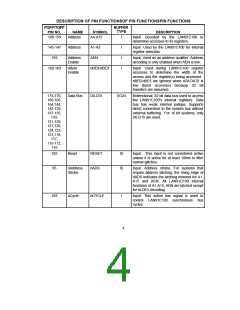
DESCRIPTION OF PIN FUNCTIONSOF PIN FUNCTIONSPIN FUNCTIONS
PQFP/TQFP
PIN NO.
BUFFER
TYPE
NAME
SYMBOL
DESCRIPTION
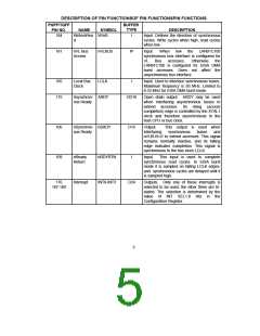
184
Write/nRea W/nR
d
I
Input. Defines the direction of synchronous
cycles. Write cycles when high, read cycles
when low.
181
nVL Bus
Access
nVLBUS
IP
Input.
synchronous bus interface is configured for
VL Bus accesses. Otherwise the
When
low
the
LAN91C100
LAN91C100 is configured for EISA DMA
burst accesses. Does not affect the
asynchronous bus interface.
105
175
Local Bus
Clock
LCLK
I
Input. Used to interface synchronous buses.
Maximum frequency is 50 MHz. Limited to
8.33 MHz for EISA DMA burst mode.
Asynchron- ARDY
ous Ready
OD16
Open drain output. ARDY may be used
when interfacing asynchronous buses to
extend accesses. Its rising (access
completion) edge is controlled by the XTAL1
clock and therefore asynchronous to the
host CPU or bus clock.
106
109
nSynchron- nSRDY
ous Ready
O16
Output.
interfacing
This output is used when
synchronous buses and
nVLBUS=0 to extend accesses. This signal
remains normally inactive, and its falling
edge indicates completion. This signal is
synchronous to the bus clock LCLK.
nReady
Return
nRDYRTN
I
Input.
This input is used to complete
synchronous read cycles. In EISA burst
mode it is sampled on falling LCLK edges,
and synchronous cycles are delayed until it
is sampled high.
176
187-189
Interrupt
INT0-INT3
O24
Outputs. Only one of these interrupts is
selected to be used; the other three are tri-
stated. The selection is determined by the
value of INT SEL1-0 bits in the
Configuration Register.
5

 SMSC [ SMSC CORPORATION ]