±15kV ESD Protected MII/RMII 10/100 Ethernet Transceiver with HP Auto-MDIX Support and flexPWR® Technology in a Small Footprint
Datasheet
5.4.7
LED Description
The PHY provides four LED signals. These provide a convenient means to determine the mode of
operation of the Phy. All LED signals are either active high or active low.
The four LED signals can be either active-high or active-low. Polarity depends upon the Phy address
latched in on reset. The LAN8700/LAN8700i senses each Phy address bit and changes the polarity of
the LED signal accordingly. If the address bit is set as level “1”, the LED polarity will be set to an active-
low. If the address bit is set as level “0”, the LED polarity will be set to an active-high.
The ACTIVITY LED output is driven active when CRS is active (high). When CRS becomes inactive,
the Activity LED output is extended by 128ms.
The LINK LED output is driven active whenever the PHY detects a valid link. The use of the 10Mbps
or 100Mbps link test status is determined by the condition of the internally determined speed selection.
The SPEED100 LED output is driven active when the operating speed is 100Mbit/s or during Auto-
negotiation. This LED will go inactive when the operating speed is 10Mbit/s or during line isolation
(register 31 bit 5).
The Full-Duplex LED output is driven active low when the link is operating in Full-Duplex mode.
5.4.8
Loopback Operation
The LAN8700/LAN8700i may be configured for near-end loopback and far loopback.
5.4.8.1
Near-end Loopback
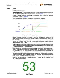
Near-end loopback is a mode that sends the digital transmit data back out the receive data signals for
testing purposes as indicated by the blue arrows in Figure 5.2.The near-end loopback mode is enabled
by setting bit register 0 bit 14 to logic one.
A large percentage of the digital circuitry is operational near-end loopback mode, because data is
routed through the PCS and PMA layers into the PMD sublayer before it is looped back. The COL
signal will be inactive in this mode, unless collision test (bit 0.7) is active. The transmitters are powered
down, regardless of the state of TXEN.
TXD
RXD
TX
RX
10/100
Ethernet
MAC
X
X
CAT-5
XFMR
Digital
Analog
SMSC
Ethernet Transceiver
Figure 5.2 Near-end Loopback Block Diagram
Revision 2.3 (04-12-11)
SMSC LAN8700/LAN8700i
DATA5S4HEET

 SMSC [ SMSC CORPORATION ]