±15kV ESD Protected MII/RMII 10/100 Ethernet Transceiver with HP Auto-MDIX Support and flexPWR® Technology in a Small Footprint
Datasheet
5.4.6
Reset
The PHY has 3 reset sources:
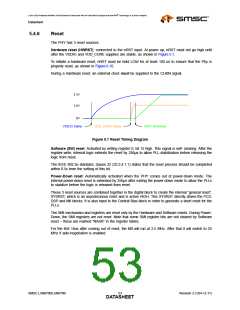
Hardware reset (HWRST): connected to the nRST input. At power up, nRST must not go high until
after the VDDIO and VDD_CORE supplies are stable, as shown in Figure 5.1.
To initiate a hardware reset, nRST must be held LOW for at least 100 us to ensure that the Phy is
properly reset, as shown in Figure 6.10.
During a Hardware reset, an external clock must be supplied to the CLKIN signal.
3.3V
1.8V
0V
VDD33 Starts
VDD_CORE Starts
nRST Released
Figure 5.1 Reset Timing Diagram
Software (SW) reset: Activated by writing register 0, bit 15 high. This signal is self- clearing. After the
register-write, internal logic extends the reset by 256µs to allow PLL-stabilization before releasing the
logic from reset.
The IEEE 802.3u standard, clause 22 (22.2.4.1.1) states that the reset process should be completed
within 0.5s from the setting of this bit.
Power-Down reset: Automatically activated when the PHY comes out of power-down mode. The
internal power-down reset is extended by 256µs after exiting the power-down mode to allow the PLLs
to stabilize before the logic is released from reset.
These 3 reset sources are combined together in the digital block to create the internal “general reset”,
SYSRST, which is an asynchronous reset and is active HIGH. This SYSRST directly drives the PCS,
DSP and MII blocks. It is also input to the Central Bias block in order to generate a short reset for the
PLLs.
The SMI mechanism and registers are reset only by the Hardware and Software resets. During Power-
Down, the SMI registers are not reset. Note that some SMI register bits are not cleared by Software
reset – these are marked “NASR” in the register tables.
For the first 16us after coming out of reset, the MII will run at 2.5 MHz. After that it will switch to 25
MHz if auto-negotiation is enabled.
SMSC LAN8700/LAN8700i
Revision 2.3 (04-12-11)
DATA5S3HEET

 SMSC [ SMSC CORPORATION ]