±15kV ESD Protected MII/RMII 10/100 Ethernet Transceiver with HP Auto-MDIX Support and flexPWR® Technology in a Small Footprint
Datasheet
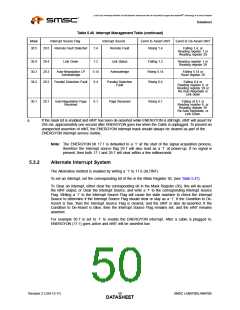
To de-assert the nINT interrupt output, either.
1. Clear the ENERGYON bit (17.1), by removing the cable, then writing a ‘1’ to register 29.7.
Or
2. Clear the Mask bit 30.1 by writing a ‘0’ to 30.1.
Table 5.47 Alternative Interrupt System Management Table
Mask
Interrupt Source Flag
ENERGYON
Interrupt Source
ENERGYON
Event to Assert
nINT
Condition to
De-Assert.
Bit to Clear
nINT
30.7
30.6
29.7
29.6
17.1
1.5
Rising 17.1
Rising 1.5
17.1 low
1.5 low
29.7
29.6
Auto-Negotiation
complete
Auto-Negotiate
Complete
30.5
30.4
30.3
29.5
29.4
29.3
Remote Fault Detected
Link Down
1.4
1.2
Remote Fault
Link Status
Rising 1.4
Falling 1.2
Rising 5.14
1.4 low
1.2 high
5.14 low
29.5
29.4
29.3
Auto-Negotiation LP
Acknowledge
5.14
Acknowledge
30.2
30.1
29.2
29.1
Parallel Detection Fault
6.4
6.1
Parallel Detection
Fault
Rising 6.4
Rising 6.1
6.4 low
6.1 low
29.2
29.1
Auto-Negotiation Page
Received
Page Received
Note: The ENERGYON bit 17.1 is defaulted to a ‘1’ at the start of the signal acquisition process,
therefore the Interrupt source flag 29.7 will also read as a ‘1’ at power-up. If no signal is
present, then both 17.1 and 29.7 will clear within a few milliseconds.
5.4
Miscellaneous Functions
5.4.1
Carrier Sense
The carrier sense is output on CRS. CRS is a signal defined by the MII specification in the IEEE 802.3u
standard. The PHY asserts CRS based only on receive activity whenever the PHY is either in repeater
mode or full-duplex mode. Otherwise the PHY asserts CRS based on either transmit or receive activity.
The carrier sense logic uses the encoded, unscrambled data to determine carrier activity status. It
activates carrier sense with the detection of 2 non-contiguous zeros within any 10 bit span. Carrier
sense terminates if a span of 10 consecutive ones is detected before a /J/K/ Start-of Stream Delimiter
pair. If an SSD pair is detected, carrier sense is asserted until either /T/R/ End–of-Stream Delimiter
pair or a pair of IDLE symbols is detected. Carrier is negated after the /T/ symbol or the first IDLE. If
/T/ is not followed by /R/, then carrier is maintained. Carrier is treated similarly for IDLE followed by
some non-IDLE symbol.
5.4.2
Collision Detect
A collision is the occurrence of simultaneous transmit and receive operations. The COL output is
asserted to indicate that a collision has been detected. COL remains active for the duration of the
collision. COL is changed asynchronously to both RX_CLK and TX_CLK. The COL output becomes
inactive during full duplex mode.
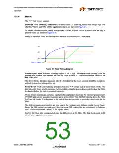
COL may be tested by setting register 0, bit 7 high. This enables the collision test. COL will be asserted
within 512 bit times of TX_EN rising and will be de-asserted within 4 bit times of TX_EN falling.
In 10M mode, COL pulses for approximately 10 bit times (1us), 2us after each transmitted packet (de-
assertion of TX_EN). This is the Signal Quality Error (SQE) signal and indicates that the transmission
was successful. The user can disable this pulse by setting bit 11 in register 27.
SMSC LAN8700/LAN8700i
Revision 2.3 (04-12-11)
DATA5S1HEET

 SMSC [ SMSC CORPORATION ]