INTERFACE MODES
The Interface modes are determined by the MFM and IDENT configuration bits in Configuration Register 3 (see
section CR03 on page 100).
PC/AT Interface Mode
When both IDENT and MFM are high the PC/AT register set is enabled, the DMA enable bit of the Digital Output
Register becomes valid, FINTR and DRQ can be hi-Z, and TC and DENSEL become active high.
PS/2 Interface Mode
When IDENT is low and MFM is high PS/2 Interface mode is selected. This mode supports the PS/2 models
50/60/80 configuration and register set. The DMA bit of the Digital Output Register becomes a “don’t care,” FINTR
and DRQ are always valid, TC and DENSEL become active low.
Model 30 Interface Mode
When both IDENT and MFM are low Model 30 Interface Mode is selected. This mode supports PS/2 Model 30
configuration and register set. The DMA enable bit of the Digital Output Register becomes valid, FINTR and DRQ
can be hi-Z, TC is active high and DENSEL is active low.
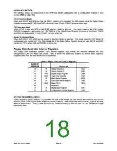
Floppy Disk Controller Internal Registers
The Floppy Disk Controller contains eight internal registers that provide the interface between the host
microprocessor and the floppy disk drives. Table 4 shows the addresses required to access these registers.
Registers other than the ones shown are not supported.
Table 4 - Status, Data and Control Registers
BASE I/O
ADDRESS
REGISTER
+0
+1
+2
+3
+4
+4
+5
+6
+7
+7
R
R
R/W
R/W
R
W
R/W
Status Register A
SRA
SRB
DOR
TDR
MSR
DSR
FIFO
Status Register B
Digital Output Register
Tape Drive Register
Main Status Register
Data Rate Select Register
Data (FIFO)
Reserved
Digital Input Register
Configuration Control Register
R
W
DIR
CCR
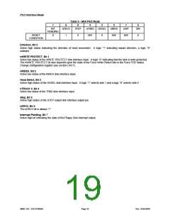
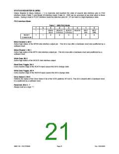
STATUS REGISTER A (SRA)
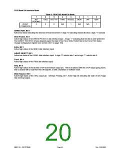
Status Register A (Base Address + 0) monitors the state of the FINTR pin and several disk interface pins in PS/2
interface mode (Table 5) and Model 30 interface mode (Table 6). SRA is read-only and can be accessed at any time
when in these modes. During a read in the PC/AT interface mode the data bus pins D0 - D7 are held in a high
impedance state.
SMSC DS – FDC37N3869
Page 18
Rev. 10/25/2000

 SMSC [ SMSC CORPORATION ]