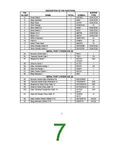
DESCRIPTION OF PIN FUNCTIONS
PIN
No./QFP
BUFFER
TYPE
NAME
TOTAL
SYMBOL
PARALLEL PORT INTERFACE (17)
68:75
66
Parallel Port Data Bus
8
1
1
1
1
1
1
1
1
1
PD[0:7]
nSLCTIN
nINIT
IO24
Printer Select
OD24/O24
67
Initiate Output
Auto Line Feed
Strobe Signal
OD24/O24
83
nALF
OD24/O24
82
nSTROBE
BUSY
OD24/O24
81
Busy Signal
I
I
I
I
I
77
Acknowledge Handshake
Paper End
nACK
80
PE
79
Printer Selected
Error at Printer
SLCT
78
nERROR
KEYBOARD/MOUSE INTERFACE (6)
59
58
57
56
64
Keyboard Data
Keyboard Clock
Mouse Data
1
1
1
1
1
KDAT
KCLK
MDAT
MCLK
IOD16P
IOD16P
IOD16P
IOD16P
O4
Mouse Clock
Keyboard Reset
KBDRST
(Note 3)
63
Gate A20
1
A20M
O4
Note 1:
For 12 bit addressing, SA0:SA11 only, nCS should be tied to GND. For 16 bit external
address qualification, address bits SA11:SA15 can be "ORed" together and applied to nCS.
The nCS pin functions as SA11 in full 16 bit Internal Address Qualification Mode. CR24.6
controls the FDC37M60x addressing modes.
Note 2:
Note 3:
The "n" as the first letter of a signal name indicates an "Active Low" signal.
KBDRST is active low.
Buffer Type Descriptions
I
IS
Input, TTL compatible.
Input with Schmitt trigger.
IOD16P Input/Output, 16mA sink, 90uA pull-up.
IO24
IO4
O4
O24
OD24
ICLK
Input/Output, 24mA sink, 12mA source.
Input/Output, 4mA sink, 2mA source.
Output, 4mA sink, 2mA source.
Output, 24mA sink, 12mA source.
Output, Open Drain, 24mA sink.
Clock Input
8

 SMSC [ SMSC CORPORATION ]