Fan Control Device with High Frequency PWM Support and Hardware Monitoring Features
Datasheet
INT_STS1 Reg
2.5V_Error
2.5V_Error (INT1[0])
2.5V_Error_En (IER1[2])
Vccp_Error
Vccp_Error (INT1[1])
Vccp_Error_En (IER1[3])
VCC_Error
VCC_Error_En (IER1[7])
5V_Error
5V_Error_En (IER1[5])
Diode 1 Limit
Diode 1_En (IER3[2])
Ambient Limit
Ambient_En (IER3[1])
Diode 2 Limit
Diode 2_En (IER3[3])
+
VCC_Error (INT1[2])
5V_Error (INT1[3])
Diode 1 Limit (INT1[4])
Ambient Limit (INT1[5])
+
Diode 2 Limit (INT1[6])
INT2 (INT1[7])
+
INT#
INT_STS2 Reg
12V_Error
12V_Error_En (IER1[6])
TACH1 Out-of-Limit
12V_Error (INT2[0])
TACH1 (INT2[2])
TACH2 (INT2[3])
TACH1_En (IER2[1])
TACH2 Out-of-Limit
TACH2 _En (IER2[2])
+
TACH3 Out-of-Limit
TACH3 _En (IER2[3])
TACH4 Out-of-Limit
TACH3 (INT2[4])
TACH4 (INT2[5])
TACH4 _En (IER2[4])
Diode 1 Fault
Diode 1_En (IER3[2])
Diode 2 Fault
Diode 1 Fault (INT2[6])
Diode 2 Fault (INT2[7])
Diode 2_En (IER3[3])
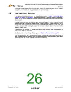
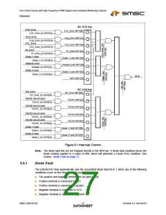
Figure 6.1 Interrupt Control
Note: The diode fault bits are not mapped directly to the INT# pin. A diode fault condition forces the
diode reading register to a value of 80h, which will generate a Diode Error condition. See
section Diode Fault on page 27.
6.4.1
Diode Fault
The EMC6D103 Chip automatically sets the associated diode fault bit to 1 when any of the following
conditions occur on the Remote Diode pins:
■
■
■
■
■
The positive and negative terminal are an open circuit.
Positive terminal is connected to VCC
Positive terminal is connected to ground
Negative terminal is connected to VCC
Negative terminal is connected to ground
SMSC EMC6D103
Revision 0.4 (04-04-05)
DATA2S7HEET

 SMSC [ SMSC CORPORATION ]