RPM-Based PWM Fan Controller
Datasheet
During normal operation, if the fan stops for any reason (including low drive), the RPM-based Fan
Speed Control Algorithm will attempt to restart the fan. Setting the Fan Minimum Drive Register to a
setting that will maintain fan operation is a useful way to avoid potential fan oscillations as the control
circuitry attempts to drive it at a level that cannot support fan operation.
The Fan Minimum Drive Register is software locked.
5.15
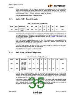
Valid TACH Count Register
Table 5.25 Valid TACH Count Register
ADDR
R/W
REGISTER
B7
B6
B5
B4
B3
B2
B1
B0
DEFAULT
Valid TACH
Count
39h
R/W
4096
2048
1024
512
256
128
64
32
F5h
The Valid TACH Count register stores the maximum TACH Reading Register value to indicate that the
fan is spinning properly. The value is referenced at the end of the Spin Up Routine to determine if the
fan has started operating and decide if the device needs to retry. See Equation [2] in Section 5.18 for
translating the count to an RPM.
If the TACH Reading Register value exceeds the Valid TACH Count Register (indicating that the Fan
RPM is below the threshold set by this count), then a stalled fan is detected. In this condition, the
algorithm will automatically begin its Spin Up Routine.
If a TACH Target setting is set above the Valid TACH Count setting, then that setting will be ignored
and the algorithm will use the current fan drive setting.
The Valid TACH Count register is software locked.
5.16
Fan Drive Fail Band Registers
Table 5.26 Fan Drive Fail Band Registers
ADDR
R/W
REGISTER
B7
B6
B5
B4
B3
B2
B1
B0
DEFAULT
Fan Drive
Fail Band
Low Byte
3Ah
R/W
16
8
4
2
1
-
-
-
00h
Fan Drive
Fail Band
High Byte
3Bh
R/W
4096 2048 1024
512
256
128
64
32
00h
The Fan Drive Fail Band Registers store the number of tach counts used by the Fan Drive Fail
detection circuitry. This circuitry is activated when the fan drive setting high byte is at FFh. When it is
enabled, the actual measured fan speed is compared against the target fan speed. These registers
are only used when the FSC is active.
This circuitry is used to indicate that the target fan speed at full drive is higher than the fan is actually
capable of reaching. If the measured fan speed does not exceed the target fan speed minus the Fan
Drive Fail Band Register settings for a period of time longer than set by the DRIVE_FAIL_CNTx[1:0]
bits, then the DRIVE_FAIL status bit will be set and an interrupt generated.
SMSC EMC2301
Revision 1.1 (10-12-09)
DATA3S5HEET

 SMSC [ SMSC CORPORATION ]