RPM-Based PWM Fan Controller
Datasheet
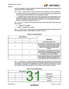
Table 5.16 Error Range Options (continued)
ERR_RNG[1:0]
1
0
OPERATION
200 RPM
1
1
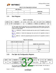
5.11
Gain Register
Table 5.17 Gain Register
ADDR
R/W
R/W
REGISTER
B7
B6
B5
B4
B3
B2
B1
B0
DEFAULT
35h
Gain Register
-
-
GAIND[1:0]
GAINI[1:0]
GAINP[1:0]
2Ah
The Gain register stores the gain terms used by the proportional and integral portions of the RPM-
based Fan Speed Control Algorithm. These gain terms are used as the KD, KI, and KP gain terms in
a classic PID control solution.
Bits 5 - 4 - GAINDX[1:0] - Controls the derivative gain term used by the FSC algorithm as shown in
Table 5.18.
Bits 3-2 - GAINIX[1:0] - Controls the integral gain term used by the FSC algorithm as shown in
Table 5.18.
Bits 1-0 - GAINP[1:0] - Controls the proportional gain term used by the FSC algorithm as shown in
Table 5.18.
Table 5.18 Gain Decode
GAIND OR GAINP OR GAINI [1:0]
1
0
RESPECTIVE GAIN FACTOR
0
0
1
1
0
1
0
1
1x
2x
4x (default)
8x
5.12
Fan Spin Up Configuration Register
Table 5.19 Fan Spin Up Configuration Register
ADDR
36h
R/W
REGISTER
B7
B6
B5
B4
B3
B2
B1
B0
DEFAULT
Fan Spin Up
Configuration
DRIVE_FAIL_
CNT [1:0]
SPINUP_TIME
[1:0]
R/W
NOKICK
SPIN_LVL[2:0]
19h
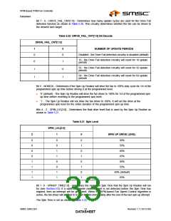
The Fan Spin Up Configuration register controls the settings of Spin Up Routine. The Fan Spin Up
Configuration register is software locked.
Revision 1.1 (10-12-09)
SMSC EMC2301
DATA3S2HEET

 SMSC [ SMSC CORPORATION ]