RPM-Based PWM Fan Controller
Datasheet
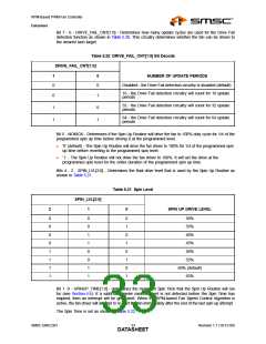
Bit 7 - 6 - DRIVE_FAIL_CNT[1:0] - Determines how many update cycles are used for the Drive Fail
detection function as shown in Table 5.20. This circuitry determines whether the fan can be driven to
the desired tach target.
Table 5.20 DRIVE_FAIL_CNT[1:0] Bit Decode
DRIVE_FAIL_CNT[1:0]
1
0
NUMBER OF UPDATE PERIODS
0
0
Disabled - the Drive Fail detection circuitry is disabled (default)
16 - the Drive Fail detection circuitry will count for 16 update
periods
0
1
1
1
0
1
32 - the Drive Fail detection circuitry will count for 32 update
periods
64 - the Drive Fail detection circuitry will count for 64 update
periods
Bit 5 - NOKICK - Determines if the Spin Up Routine will drive the fan to 100% duty cycle for 1/4 of the
programmed spin up time before driving it at the programmed level.
‘0’ (default) - The Spin Up Routine will drive the fan driver to 100% for 1/4 of the programmed spin
up time before reverting to the programmed spin level.
‘1’ - The Spin Up Routine will not drive the fan driver to 100%. It will set the drive at the
programmed spin level for the entire duration of the programmed spin up time.
Bits 4 - 2 - SPIN_LVL[2:0] - Determines the final drive level that is used by the Spin Up Routine as
shown in Table 5.21.
Table 5.21 Spin Level
SPIN_LVL[2:0]
2
1
0
SPIN UP DRIVE LEVEL
0
0
0
0
1
1
1
1
0
0
1
1
0
0
1
1
0
1
0
1
0
1
0
1
30%
35%
40%
45%
50%
55%
60% (default)
65%
Bit 1 -0 - SPINUP_TIME[1:0] - determines the maximum Spin Time that the Spin Up Routine will run
for (see Section 4.6). If a valid tachometer measurement is not detected before the Spin Time has
elapsed, then an interrupt will be generated. When the RPM-based Fan Speed Control Algorithm is
active, the fan driver will attempt to re-start the fan immediately after the end of the last spin up attempt.
The Spin Time is set as shown in Table 5.22.
SMSC EMC2301
Revision 1.1 (10-12-09)
DATA3S3HEET

 SMSC [ SMSC CORPORATION ]