RPM-Based PWM Fan Controller
Datasheet
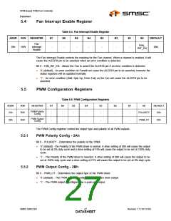
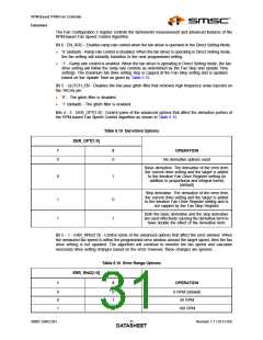
5.4
Fan Interrupt Enable Register
Table 5.4 Fan Interrupt Enable Register
ADDR
R/W
REGISTER
B7
B6
B5
B4
B3
B2
B1
B0
DEFAULT
Fan
Interrupt
Enable
FAN_
INT_EN
29h
R/W
-
-
-
-
-
-
-
00h
The Fan Interrupt Enable controls the masking for the Fan channel. When a channel is enabled, it will
cause the ALERT# pin to be asserted when an error condition is detected.
Bit 0 - FAN_INT_EN - Allows the Fan to assert the ALERT# pin if an error condition is detected.
‘0’ (default) - An error condition on Fanwill not cause the ALERT# pin to be asserted, however the
status registers will be updated normally.
‘1’ - An error condition (Stall, Spin Up, Drive Fail) on the Fan will cause the ALERT# pin to be
asserted.
5.5
PWM Configuration Registers
Table 5.5 PWM Configuration Registers
ADDR
R/W
REGISTER
B7
B6
B5
B4
B3
B2
B1
B0
DEFAULT
PWM Polarity
Config
2Ah
2Bh
R/W
-
-
-
-
-
-
-
POLARITY
00h
PWM Output
Config
R/W
-
-
-
-
-
-
-
PWM_OT
00h
The PWM Config registers control the output type and polarity of all PWM outputs.
5.5.1
PWM Polarity Config - 2Ah
Bit 0 - POLARITY - Determines the polarity of the PWM.
‘0’ (default) - the Polarity of the PWM driver is normal. A drive setting of 00h will cause the output
to be set at 0% duty cycle and a drive setting of FFh will cause the output to be set at 100% duty
cycle.
‘1’ - The Polarity of the PWM driver is inverted. A drive setting of 00h will cause the output to be
set at 100% duty cycle and a drive setting of FFh will cause the output to be set at 0% duty cycle.
5.5.2
PWM Output Config - 2Bh
Bit 0 - PWM_OT - Determines the output type of the PWM driver.
‘0’ (default) - The PWM output is configured as an open drain output.
‘1’ - The PWM output is configured as a push-pull output.
SMSC EMC2301
Revision 1.1 (10-12-09)
DATA2S7HEET

 SMSC [ SMSC CORPORATION ]