RPM-Based PWM Fan Controller
Datasheet
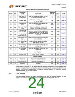
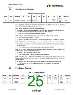
Table 5.1 EMC2301 Register Set (continued)
FUNCTION
REGISTER
NAME
DEFAULT
VALUE
ADDR
R/W
LOCK
PAGE
Fan Spin Up
Configuration
Sets the configuration values for Spin
Up Routine of the Fan driver
36h
R/W
19h
SWL
Page 32
Sets the maximum change per update
for the Fan driver
37h
38h
39h
3Ah
3Bh
3Ch
3Dh
3Eh
3Fh
R/W
R/W
R/W
R/W
R/W
R/W
R/W
R
Fan Max Step
10h
SWL
SWL
SWL
SWL
SWL
No
Page 34
Page 34
Page 35
Fan Minimum
Drive
Sets the minimum drive value for the
Fan driver
66h
(40%)
Fan Valid TACH
Count
Holds the tachometer reading that
indicates Fan is spinning properly
F5h
00h
00h
F8h
FFh
FFh
F8h
Fan Drive Fail
Band Low Byte
Stores the number of Tach counts used
to determine how the actual fan speed
must match the target fan speed at full
scale drive
Page 35
Fan Drive Fail
Band High Byte
TACH Target Low
Byte
Holds the target tachometer reading low
byte for the Fan
Page 36
Page 36
Page 36
Page 36
TACH Target High
Byte
Holds the target tachometer reading
high byte for the Fan
No
TACH Reading
High Byte
Holds the tachometer reading high byte
for the Fan
No
TACH Reading
Low Byte
Holds the tachometer reading low byte
for the Fan
R
No
Lock Register
Locks all SWL registers
Revision Registers
EF
R/W
Software Lock
00h
SWL
Page 37
FDh
FEh
FFh
R
R
R
Product ID
Manufacturer ID
Revision
Stores the unique Product ID
Stores the Manufacturer ID
Revision
37h
5Dh
80h
No
No
No
Page 37
Page 38
Page 38
During Power-On-Reset (POR), the default values are stored in the registers. A POR is initiated when
power is first applied to the part and the voltage on the VDD supply surpasses the POR level as
specified in the electrical characteristics. Any reads to undefined registers will return 00h. Writes to
undefined registers will not have an effect.
5.1.1
Lock Entries
The Lock Column describes the locking mechanism, if any, used for individual registers. All SWL
registers are Software Locked and therefore made read-only when the LOCK bit is set.
Revision 1.1 (10-12-09)
SMSC EMC2301
DATA2S4HEET

 SMSC [ SMSC CORPORATION ]