RPM-Based PWM Fan Controller
Datasheet
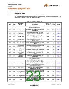
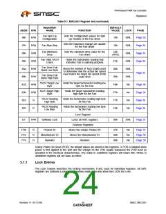
Chapter 5 Register Set
5.1
Register Map
The following registers are accessible through the SMBus Interface. All register bits marked as ‘-’ will
always read ‘0’. A write to these bits will have no effect.
Table 5.1 EMC2301 Register Set
REGISTER
NAME
DEFAULT
VALUE
ADDR
R/W
FUNCTION
LOCK
PAGE
Configuration and control
Configures the clocking and watchdog
functionality
20h
24h
25h
26h
27h
29h
2Ah
2Bh
2Dh
R/W
R-C
R-C
R-C
R-C
R/W
R/W
R/W
R/W
Configuration
Fan Status
40h
00h
00h
00h
00h
00h
00h
00h
00h
SWL
No
No
No
No
No
No
No
No
Page 25
Page 25
Page 25
Page 25
Page 25
Page 27
Page 27
Page 27
Page 28
Stores the status bits for the RPM-
based Fan Speed Control Algorithm
Stores status bits associated with a
stalled fan
Fan Stall Status
Fan Spin Status
Drive Fail Status
Stores status bits associated with a
spin-up failure
Stores status bits associated with drive
failure
Fan Interrupt
Enable Register
Controls the masking of interrupts on all
fan related channels
PWM Polarity
Config
Configures Polarity of the PWM driver
PWM Output
Config
Configures Output type of the PWM
driver
PWM Base
Frequency
Selects the base frequency for the
PWM output
Fan Control Registers
Always displays the most recent fan
driver input setting for the Fan. If the
RPM-based Fan Speed Control
Algorithm is disabled, allows direct user
control of the fan driver.
30h
R/W
Fan Setting
PWM Divide
00h
No
Page 28
Stores the divide ratio to set the
frequency for the Fan
31h
32h
33h
35h
R/W
R/W
R/W
R/W
01h
2Bh
28h
2Ah
No
No
Page 29
Page 29
Page 30
Page 32
Sets configuration values for the RPM-
based Fan Speed Control Algorithm for
the Fan driver
Fan Configuration
1
Fan Configuration
2
Sets additional configuration values for
the Fan driver
SWL
SWL
Holds the gain terms used by the RPM-
based Fan Speed Control Algorithm for
the Fan driver
Gain
SMSC EMC2301
Revision 1.1 (10-12-09)
DATA2S3HEET

 SMSC [ SMSC CORPORATION ]