RPM-Based Fan Controller with HW Thermal Shutdown
Datasheet
2.2
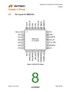
Pin Description for EMC2102
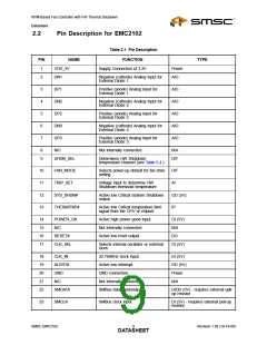
Table 2.1 Pin Description
PIN
NAME
VDD_3V
FUNCTION
TYPE
1
2
Supply Connection of 3.3V.
Power
AIO
DN1
DP1
DN2
DP2
DN3
DP3
Negative (cathode) Analog Input for
External Diode 1.
3
4
5
6
7
Positive (anode) Analog Input for
External Diode 1.
AIO
AIO
AIO
AIO
AIO
Negative (cathode) Analog Input for
External Diode 2.
Positive (anode) Analog Input for
External Diode 2.
Negative (cathode) Analog Input for
External Diode 3.
Positive (anode) Analog Input for
External Diode 3.
8
9
N/C
Not internally connected.
N/A
DIT
SHDN_SEL
Determines HW Shutdown
temperature channel (see Table 5.4.)
10
11
12
13
FAN_MODE
TRIP_SET
Selects power-up default for fan drive
setting.
DIT
Voltage input to determine HW
Shutdown threshold temperature
AI
SYS_SHDN#
THERMTRIP#
Active low Critical System Shutdown
output
OD (5V)
IP
Active low Critical temperature limit
signal from the CPU or chipset.
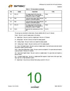
14
15
16
17
POWER_OK
N/C
Active high power good input.
Not internally connected.
Active low reset output.
DI (5V)
N/A
RESET#
CLK_SEL
DO
Selects internal oscillator or external
clock.
DI (5V)
18
19
20
21
22
CLK_IN
ALERT#
GND
32.768KHz clock input.
Active low interrupt.
DI (5V)
OD (5V)
Power
N/A
GND connection.
N/C
Not internally connected.
SMBus data input/output.
SMDATA
DIOD (5V) - requires external upll-
up resistor
23
SMCLK
SMBus clock input.
DI (5V) - requires external pull-up
resistor
SMSC EMC2102
9
Revision 1.95 (10-19-06)
DATASHEET

 SMSC [ SMSC CORPORATION ]