RPM-Based Fan Controller with HW Thermal Shutdown
Datasheet
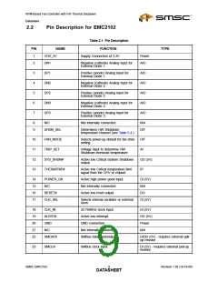
Table 2.1 Pin Description (continued)
PIN
NAME
VDD_5V
FUNCTION
TYPE
24
5V supply input for the linear fan
driver. Both VDD_5V pins should be
connected to same 5V supply.
Power
25
26
27
FAN
Linear fan drive signal. Both FAN pins
should be connected together.
AO
FAN
Linear fan drive signal. Both FAN pins
should be connected together.
AO
VDD_5V
5V supply input for the linear fan
driver. Both VDD_5V pins should be
connected to same 5V supply.
Power
28
TACH
Input from the tachometer pin of the
fan.
DI (5V)
The pin type are described in detail below. All pins labelled with (5V) are 5V tolerant.:
Power - this pin is used to supply power to the device.
DI - Digital Input - this pin is used as a digital input. This pin is 5V tolerant.
AI - Analog Input - this pin is used as an input for analog signals..
AO - Analog Output - this pin is used as an output for analog signals.
AIO - Analog Input / Output - this pin is used as an I/O for analog signals.
DO - Push / Pull Digital Output - this pin is used as a digital output. It can both source and sink current
and doesn’t require a pull-up resistor.
DIOD - Open Drain Digital Input / Output - this pin is used as an digital I/O. It is open drain and requires
a pull-up resistor. This pin is 5V tolerant.
OD - Open Drain Digital Output - this pin is used as a digital output. It is open drain and requires a
pull-up resistor.
DIT - Tri-stated Digital Input - this pin is a digital input that supports 3 logic levels at the input: logic
high, logic low, or high impedance (open).
IP - Digital Input - this pin has an internal 30uA pull-up current to VDD_3V
Revision 1.95 (10-19-06)
SMSC EMC2102
DATA1S0HEET

 SMSC [ SMSC CORPORATION ]