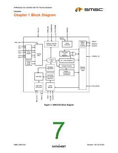
RPM-Based Fan Controller with HW Thermal Shutdown
Datasheet
Chapter 3 Electrical Specifications
3.1
Absolute Maximum Ratings
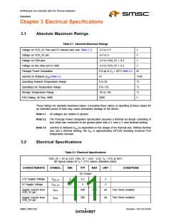
Table 3.1 Absolute Maximum Ratings
Voltage on VDD_5V Pins and 5V tolerant pins (see Table 2.1)
Voltage on VDD_3V pin
-0.3 to 6.5
V
-0.3 to 4
V
Voltage on FAN pins
-0.3 to VDD_5V + 0.3
V
Voltage on any other pin to GND
Package Power Dissipation
-0.3 to VDD_3V + 0.3
V
0.9 up to TA = 85°C Note 3.2
W
°C/W
°C
°C
°C
V
Junction to Ambient (θJA) Note 3.3
Operating Ambient Temperature Range
Operating Die Temperature Range
Storage Temperature Range
37
0 to 85
0 to 125
-55 to 150
2000
ESD Rating, All Pins, HBM
These ratings are absolute maximum values. Exceeding these values or operating at these values for
an extended period of time may cause permanent damage to the device.
Note 3.1 All voltages are relative to ground.
Note 3.2 The Package Power Dissipation specification assumes a thermal via design consisting of
four 20mil vias connected to the ground plane with a 3.1mm x 3.1mm thermal landing.
Note 3.3 Junction to Ambient (θJA) is dependent on the design of the thermal vias. Without thermal
vias and a thermal landing, the θJA is approximately 60°C/W including localized PCB
temperature increase.
3.2
Electrical Specifications
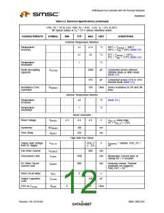
Table 3.2 Electrical Specifications
VDD_3V = 3V to 3.6V, VDD_5V = 4.6V - 5.5V, TA = 0°C to 85°C
all Typical values at TA = 27°C unless otherwise noted.
CHARACTERISTIC
SYMBOL
MIN
TYP
MAX
UNIT
CONDITIONS
DC Power
3.3V Supply Voltage
5V Supply Voltage
VDD_3V
VDD_5V
IDD3
3
3.3
5
3.6
5.5
750
V
V
4.6
Supply Current from
VDD_3V pin
500
uA
Fan Driver enabled
Fan Driver enabled
Supply Current from
VDD_5V pin
IDD5
200
uA
SMSC EMC2102
Revision 1.95 (10-19-06)
DATAS11HEET

 SMSC [ SMSC CORPORATION ]