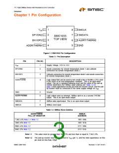
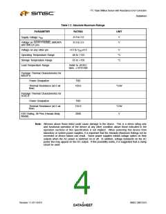
1°C Triple SMBus Sensor with Resistance Error Correction
Datasheet
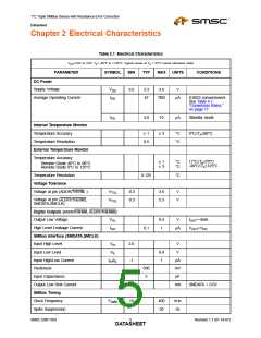
Table 2.1 Electrical Characteristics (continued)
V
=3.0V to 3.6V, T = -40°C to +125°C, Typical values at T = 27°C unless otherwise noted
A A
DD
PARAMETER
SYMBOL
MIN
TYP
MAX
UNITS
CONDITIONS
Bus free time Start to Stop
Hold time Start
TBUF
1.3
0.6
0.6
0.6
0.3
100
μs
μs
μs
μs
μs
ns
THD:STA
TSU:STA
TSU:STO
THD:DAT
TSU:DAT
Setup time Start
Setup time Stop
Data Hold Time
Data Setup Time
Clock Low Period
TLOW
THIGH
TF
1.3
0.6
*
μs
μs
ns
ns
Clock High Period
Clock/Data Fall Time
Clock/Data Rise Time
300
*Min = 20+0.1Cb ns
*Min = 20+0.1Cb ns
TR
*
300
Note
2.1
Capacitive Load (each bus line)
Cb
0.6
400
pF
Note 2.1 300nS rise time max is required for 400kHz bus operation. For lower clock frequencies,
the maximum rise time is (0.1/FSMB)+50nS
Revision 1.1 (01-19-07)
6
SMSC EMC1033
DATASHEET

 SMSC [ SMSC CORPORATION ]