ST7781
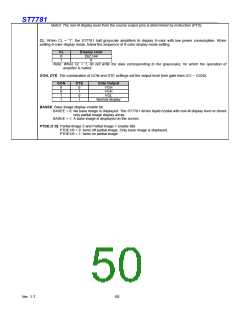
Note2: The gate output level in non-display drive period is controlled by the PTG setting (off-scan mode).
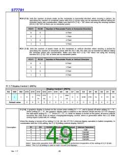
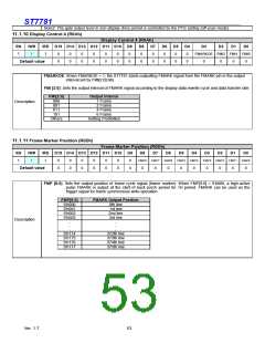
11.1.10 Display Control 4 (R0Ah)
Display Control 4 (R0Ah)
RS
/WR
/RD D15 D14 D13 D12 D11 D10 D9
D8
D7
D6
0
D5
0
D4
0
D3
D2
D1
D0
0
0
0
0
0
0
0
0
0
0
0
0
0
0
0
0
0
FMARKOE FMI2 FMI1 FMI0
1
↑
1
0
0
0
0
0
0
0
0
Default value
FMARKOE: When FMARKOE = 1, the ST7781 starts outputting FMARK signal from the FMARK pin in the output
interval set by FMI[2:0] bits
FMI [2:0]: Sets the output interval of FMARK signal according to the display data rewrite cycle and data transfer rate.
FMI[2:0]
000
001
Output Interval
1 Frame
Description
2 Frame
011
4 Frame
101
6 Frame
Others
Setting Prohibited
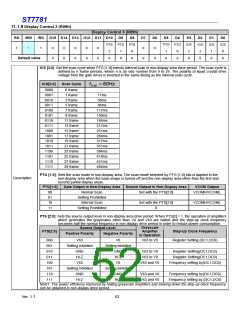
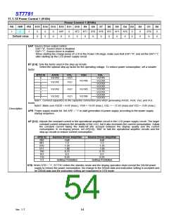
11.1.11 Frame Marker Position (R0Dh)
Frame Marker Position (R0Dh)
/RD D15 D14 D13 D12 D11 D10 D9 D8 D7
RS
/WR
D6
D5
D4
D3
D2
D1
D0
FMP8 FMP7 FMP6 FMP5 FMP4 FMP3 FMP2 FMP1 FMP0
0
0
0
0
0
0
0
0
0
0
0
0
0
0
1
↑
1
0
0
0
0
0
0
0
0
0
Default value
FMP [8:0]: Sets the output position of frame cycle signal (frame marker). When FMP[8:0] = 9’h000, a high-active
pulse FMARK is output at the start of back porch period for 1H period. FMARK can be used as the
trigger signal for frame synchronous write operation.
FMP[8:0]
9’h000
9’h001
FMARK Output Position
0th line
1st line
2nd line
9’h002
9’h003
3rd line
Description
.
.
.
.
.
.
9’h174
9’h175
9’h176
9’h177
372th line
373th line
374th line
375th line
Ver. 1.7
53

 SITRONIX [ SITRONIX TECHNOLOGY CO., LTD. ]