ST7735
9.9 Address Counter
The address counter sets the addresses of the display data RAM for writing and reading.
Data is written pixel-wise into the RAM matrix of DRIVER. The data for one pixel or two pixels is collected (RGB 6-6-6-bit),
according to the data formats. As soon as this pixel-data information is complete the “Write access” is activated on the RAM.
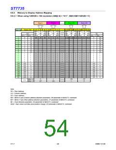
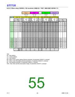
The locations of RAM are addressed by the address pointers. The address ranges are X=0 to X=131 (83h) and Y=0 to
Y=161 (A1h). Addresses outside these ranges are not allowed. Before writing to the RAM, a window must be defined that
will be written. The window is programmable via the command registers XS, YS designating the start address and XE, YE
designating the end address.
For example the whole display contents will be written, the window is defined by the following values: XS=0 (0h) YS=0 (0h)
and XE=127 (83h), YE=161 (A1h).
In vertical addressing mode (MV=1), the Y-address increments after each byte, after the last Y-address (Y=YE), Y wraps
around to YS and X increments to address the next column. In horizontal addressing mode (V=0), the X-address
increments after each byte, after the last X-address (X=XE), X wraps around to XS and Y increments to address the next
row. After the every last address (X=XE and Y=YE) the address pointers wrap around to address (X=XS and Y=YS).
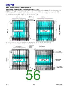
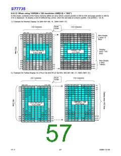
For flexibility in handling a wide variety of display architectures, the commands “CASET, RASET and MADCTL” (see
section 10 command list), define flags MX and MY, which allows mirroring of the X-address and Y-address. All
combinations of flags are allowed. Section 9.10 show the available combinations of writing to the display RAM. When MX,
MY and MV will be changed the data bust be rewritten to the display RAM.
For each image condition, the controls for the column and row counters apply as section 9.10 below
Condition
Column Counter
Return to
Row Counter
Return to
When RAMWR/RAMRD command is accepted
Complete Pixel Read / Write action
The Column counter value is larger than “End Column (XE)”
“Start Column (XS)”
Increment by 1
Return to
“Start Row (YS)”
No change
Increment by 1
“Start Column (XS)”
Return to
The Column counter value is larger than “End Column (XE)” and the Row
counter value is larger than “End Row (YE)”
Return to
“Start Column (XS)”
“Start Row (YS)”
V1.7
58
2009-12-04

 SITRONIX [ SITRONIX TECHNOLOGY CO., LTD. ]