ST7735
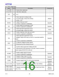
6.4 Driver output pins
Name
I/O
O
Description
Connect pin
S1 to S396
G1 to G162
- Source driver output pins.
- Gate driver output pins.
-
-
O
VCI1
I/O - Hi-Z
- Power input pin for analog circuits.
-
AVDD
I
- In normal usage, connect it to AVDDO.
- AVDD = 5.3V.
AVDDO
- Output of step-up circuit 1
AVDDO
VCL
O
O
I
Capacitor
Capacitor
VGHO
- Connect a capacitor for stabilization.
- A power supply pin for generating VCOML.
- Connect a capacitor for stabilization.
- Power input pin for gate driver circuit.
- In normal usage, connect it to VGHO.
VGH
- Positive output pin of the step-up circuit 2.
- Connect a capacitor for stabilization.
VGHO
O
Capacitor
- Power input pin for gate driver circuit.
- Negative output of the step-up circuit 2 is connected inside the
driver.
VGL
VREF
GVDD
I
Capacitor
- Connect a capacitor for stabilization.
- A reference voltage for power system.
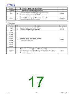
-This test pin for Driver vender test used.
O
O
-
-
- A power output of grayscale voltage generator.
- When internal GVDD generator is not used, connect an external
power supply (AVDD-0.5V) to this pin.
- Positive voltage output of VCOM.
- Connect a capacitor for stabilization.
VCOMH
VCOML
O
O
O
O
Capacitor
Capacitor
- Negative voltage output of VCOM.
- Connect a capacitor for stabilization.
Common
electrode
VCOM
- A power supply for the TFT-LCD common electrode.
Step-up
C11P, C11N
- Capacitor connecting pins for step-up circuit 1 (for AVDDO)
Capacitor
C22P, C22N
C23P, C23N
C41P, C41N
- Capacitor connecting pins for step-up circuit 2 and 4 (for VGHO,
VGL, VCL)
Step-up
O
Capacitor
V1.7
16
2009-12-04

 SITRONIX [ SITRONIX TECHNOLOGY CO., LTD. ]