ST7735
6
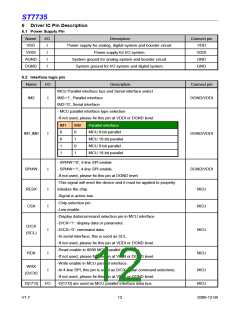
Driver IC Pin Description
6.1 Power Supply Pin
Name
VDD
I/O
Description
Connect pin
VDD
I
I
I
I
Power supply for analog, digital system and booster circuit.
Power supply for I/O system.
VDDI
VDDI
AGND
DGND
System ground for analog system and booster circuit.
System ground for I/O system and digital system.
GND
GND
6.2 Interface logic pin
Name
I/O
Description
MCU Parallel interface bus and Serial interface select
IM2=’1’, Parallel interface
Connect pin
DGND/VDDI
IM2
I
IM2=’0’, Serial interface
- MCU parallel interface type selection
-If not used, please fix this pin at VDDI or DGND level.
IM1
0
IM0
0
Parallel interface
MCU 8-bit parallel
MCU 16-bit parallel
MCU 9-bit parallel
MCU 18-bit parallel
IM1,IM0
I
I
DGND/VDDI
DGND/VDDI
0
1
1
0
1
1
- SPI4W=’0’, 3-line SPI enable.
SPI4W
- SPI4W=’1’, 4-line SPI enable.
-If not used, please fix this pin at DGND level.
-This signal will reset the device and it must be applied to properly
initialize the chip.
RESX
CSX
I
I
MCU
MCU
-Signal is active low.
-Chip selection pin
-Low enable.
-Display data/command selection pin in MCU interface.
-D/CX=’1’: display data or parameter.
-D/CX=’0’: command data.
D/CX
(SCL)
I
I
MCU
MCU
-In serial interface, this is used as SCL.
-If not used, please fix this pin at VDDI or DGND level.
-Read enable in 8080 MCU parallel interface.
-If not used, please fix this pin at VDDI or DGND level.
-Write enable in MCU parallel interface.
-In 4-line SPI, this pin is used as D/CX (data/ command selection).
-If not used, please fix this pin at VDDI or DGND level.
-D[17:0] are used as MCU parallel interface data bus.
RDX
WRX
I
MCU
(D/CX)
D[17:0]
I/O
MCU
V1.7
12
2009-12-04

 SITRONIX [ SITRONIX TECHNOLOGY CO., LTD. ]